CSP 11-34F2-D-M-ST
CSP 11-34F2-D-M-ST
- 1 x connector plug M12, 8-pole
- Actuation from side
- with On-site acknowledgment
- NOTICE: Not available! (Replacement: RSS 36 I)
- Thermoplastic enclosure
- Electronic contact-free, coded system
- Tampering protection by paired coding of sensor and actuator
- Misaligned actuation possible
- High repeat accuracy of the switching points
- Max. length of the sensor chain 200 m
- 2 short-circuit proof PNP safety outputs
- Integral cross-short, wire-breakage and external voltage monitoring of the safety cables up to the control cabinet
Ordering data
| Note (Delivery capacity) |
Not available! |
| Product type description |
CSP 11-34F2-D-M-ST |
| Article number (order number) |
101208005 |
| EAN (European Article Number) |
4030661382029 |
| eCl@ss number, version 12.0 |
27-27-26-06 |
| eCl@ss number, version 11.0 |
27-27-24-04 |
| eCl@ss number, version 9.0 |
27-27-24-04 |
| ETIM number, version 7.0 |
EC001487 |
| ETIM number, version 6.0 |
EC001487 |
Approvals - Standards
| Certificates |
cULus |
General data
| Standards |
EN ISO 13849-1 EN IEC 60947-5-3 EN IEC 61508 |
| Working principle |
inductive |
| Housing construction form |
Block |
| Installation conditions (mechanical) |
not flush |
| Sensor topology |
Sensor for series wiring |
| Housing material |
Glass-fibre, reinforced thermoplastic |
| Active area |
Glass-fibre, reinforced thermoplastic |
| Reaction time, maximum |
30 ms |
| Duration of risk, maximum |
60 ms |
| Gross weight |
140 g |
General data - Features
| Diagnostic output |
Yes |
| Short circuit detection |
Yes |
| Cross-circuit detection |
Yes |
| Safety functions |
Yes |
| Cascadable |
Yes |
| Input for reset pushbutton, with edge monitoring |
Yes |
| Input for enabling pushbutton, suitable for automatic start |
Yes |
| On-site acknowledgment |
Yes |
| Integral system diagnostics, status |
Yes |
| Number of LEDs |
3 |
| Number of semi-conductor outputs with signaling function |
1 |
| Number of fail-safe digital outputs |
2 |
| Number of series-wiring of sensors |
31 |
Safety classification
| Standards |
EN IEC 60947-5-3 EN IEC 61508 |
| Performance Level, up to |
e |
| Category |
4 |
| PFH value |
3.60 x 10⁻⁹ /h |
| Safety Integrity Level (SIL), suitable for applications in |
3 |
| Mission time |
20 Year(s) |
Mechanical data
| Actuating panels |
lateral |
| Active area |
lateral |
Mechanical data - Switching distances
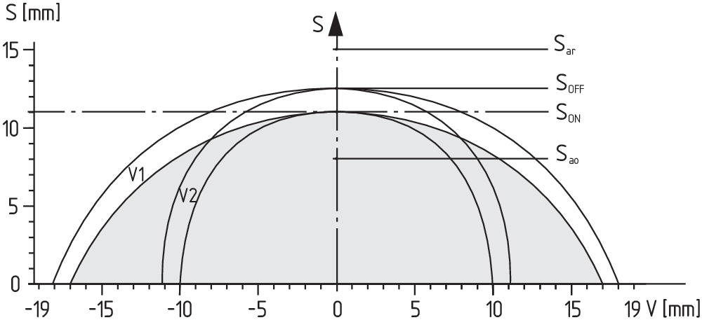
| Switch distance, typical |
11 mm |
| Assured switching distance "ON" Sao |
8 mm |
| Assured switching distance "OFF" Sar |
15 mm |
| Note (switching distance) |
All switching distances in accordance EN IEC 60947-5-3 |
| Hysteresis (Switching distance), maximum |
1.5 mm |
| Repeat accuracy R |
0.5 mm |
| Note (Repeat accuracy R) |
Axial offset: The long side allows for a maximum height misalignment (x) of sensor and actuator of 30 mm (e.g. mounting tolerance or due to guard door sagging). The axial misalignment (y) is max. ± 8 mm. |
Mechanical data - Connection technique
| Note (length of the sensor chain) |
Cable length and cross-section change the voltage drop dependiing on the output current |
| Termination |
Connector plug M12, 8-pole |
Mechanical data - Dimensions
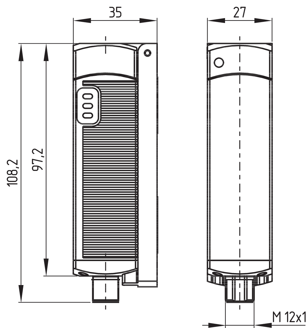
| Length of sensor |
27 mm |
| Width of sensor |
35 mm |
| Height of sensor |
108.2 mm |
Ambient conditions
| Degree of protection |
IP65 IP67 |
| Ambient temperature |
-25 ... +70 °C |
| Storage and transport temperature |
-25 ... +85 °C |
| Resistance to vibrations |
10 … 55 Hz, amplitude 1 mm |
| Restistance to shock |
30 g / 11 ms |
| Protection class |
II |
Ambient conditions - Insulation values
| Rated insulation voltage Ui |
32 VAC/DC |
| Rated impulse withstand voltage Uimp |
0.8 kV |
| Overvoltage category |
III |
| Degree of pollution |
3 |
Electrical data
| Operating voltage |
24 VDC -15 % / +10 % (stabilised PELV power supply) |
| No-load supply current I0, typical |
100 mA |
| Rated operating voltage |
24 VDC |
| Operating current |
600 mA |
| Required rated short-circuit current |
100 A |
| Utilisation category DC-12 |
24 VDC |
| Utilisation category DC-12 |
0.05 A |
| Utilisation category DC-13 |
24 VDC |
| Utilisation category DC-13 |
0.05 A |
| Note (Electrical data, Fuse rating) |
(Circuit breaker) |
| Switching frequency, approx. |
3 Hz |
| Electrical fuse rating, maximum |
2 A |
Electrical data - Safety digital outputs
| Rated operating current (safety outputs) |
250 mA |
| Output current, (fail-safe output), maximum |
0.25 A |
| Design of control elements |
p-type |
| Voltage drop Ud, maximum |
0.5 V |
| Leakage current Ir, maximum |
0.5 mA |
| Voltage, Utilisation category DC-12 |
24 VDC |
| Current, Utilisation category DC-12 |
0.25 A |
| Voltage, Utilisation category DC-13 |
24 VDC |
| Current, Utilisation category DC-13 |
0.25 A |
Electrical data - Digital Output
| Design of control elements |
p-type |
Electrical data - Diagnostic outputs
| Operating current |
50 mA |
| Voltage drop Ud, maximum |
5 V |
| Voltage, Utilisation category DC-12 |
24 VDC |
| Current, Utilisation category DC-12 |
0.05 A |
| Utilisation category DC-12 |
24 VDC / 0.05 A |
Electrical data - Electromagnetic compatibility (EMC)
| Interfering radiation |
IEC 61000-6-4 |
| EMC rating |
IEC 61000-6-2 |
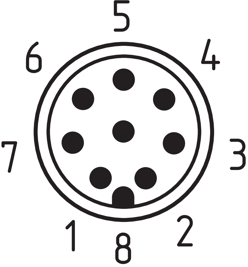
Pin assignment
| PIN 1 |
1A1 Ue: (1) |
| PIN 2 |
X1 Safety input 1 |
| PIN 3 |
A2 GND |
| PIN 4 |
Y1 Safety output 1 |
| PIN 5 |
OUT Diagnostic output OUT |
| PIN 6 |
X2 Safety input 2 |
| PIN 7 |
Y2 Safety output 2 |
| PIN 8 |
IN On-site acknowledgment |
Scope of delivery
| Scope of delivery |
Actuator must be ordered separately. |
Accessory
| Recommendation (actuator) |
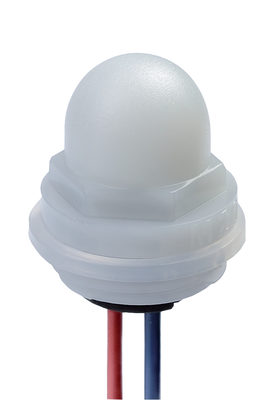
CSP 34-S-1 |
| Recommended safety switchgear |
PROTECT PSC1 SRB-E-301ST SRB-E-201LC |
Note
| Note (General) |
When safety gate monitoring by the safety sensor CSP 34F2 is required, an acknowledge button should be positioned so that the danger area can be viewed. When the button is pushed, a 24 VDC signal is generated at the reset input of the CSP 34F2. If the gate is closed the safety outputs are released with the negative signal edge. After the gate is opened it needs to be acknowledge before it can be released again. On-site acknowledgment |
Language filter
Datasheet
Operating instructions and Declaration of conformity
UL Certificate
Wiring example (electr. wiring)
Brochure
SISTEMA-VDMA library
Download the latest version of Adobe Reader
Product picture (catalogue individual photo)
ID: kcss3f17
| 201.6 kB | .jpg | 352.778 x 120.29700000000001 mm - 1000 x 341 px - 72 dpi
| 20.2 kB | .png | 74.083 x 25.400000000000002 mm - 210 x 72 px - 72 dpi
| 20.0 kB | .png | 74.083 x 74.083 mm - 210 x 210 px - 72 dpi
| 1.5 MB | .png | 200 x 68.3 mm - 2000 x 683 px - 254 dpi
| 27.5 kB | .jpg | 123.47200000000001 x 41.981 mm - 350 x 119 px - 72 dpi
Dimensional drawing basic component
Operating principle

Clipart

Characteristic curve
101208465 CSP 34-S-1-02
- Actuation from side
- actuator code 2
- 20 different actuator codes available
101208466 CSP 34-S-1-03
- Actuation from side
- actuator code 3
- 20 different actuator codes available
101208467 CSP 34-S-1-04
- Actuation from side
- actuator code 4
- 20 different actuator codes available
101208468 CSP 34-S-1-05
- Actuation from side
- actuator code 5
- 20 different actuator codes available
101208469 CSP 34-S-1-06
- Actuation from side
- actuator code 6
- 20 different actuator codes available
101208470 CSP 34-S-1-07
- Actuation from side
- actuator code 7
- 20 different actuator codes available
101208471 CSP 34-S-1-08
- Actuation from side
- actuator code 8
- 20 different actuator codes available
101208472 CSP 34-S-1-09
- Actuation from side
- actuator code 9
- 20 different actuator codes available
101208473 CSP 34-S-1-10
- Actuation from side
- actuator code 10
- 20 different actuator codes available
101208474 CSP 34-S-1-11
- Actuation from side
- actuator code 11
- 20 different actuator codes available
101208475 CSP 34-S-1-12
- Actuation from side
- actuator code 12
- 20 different actuator codes available
101208476 CSP 34-S-1-13
- Actuation from side
- actuator code 13
- 20 different actuator codes available
101208477 CSP 34-S-1-14
- Actuation from side
- actuator code 14
- 20 different actuator codes available
101208478 CSP 34-S-1-15
- Actuation from side
- actuator code 15
- 20 different actuator codes available
101208479 CSP 34-S-1-16
- Actuation from side
- actuator code 16
- 20 different actuator codes available
101208480 CSP 34-S-1-17
- Actuation from side
- actuator code 17
- 20 different actuator codes available
101208481 CSP 34-S-1-18
- Actuation from side
- actuator code 18
- 20 different actuator codes available
101208464 CSP 34-S-1-01
- Actuation from side
- actuator code 1
- Sensor and actuator must be ordered separately.

103009970 SRB-E-201LC
- Plug-in screw terminals with coding
- STOP 0 Function
- 1 oder 2-channel control
- Start button / Auto-start
- 2 Safety outputs 2 A
- 1 Signalling output
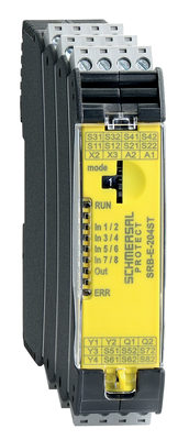
103009973 SRB-E-204ST
- Plug-in screw terminals with coding
- STOP 0 Function
- Monitoring of 4 sensors
- Start button / Auto-start
- 2 Safety outputs
- 4 Signalling outputs

103007672 SRB-E-301ST
- Plug-in screw terminals with coding
- STOP 0 Function
- 1 oder 2-channel control
- Start button / Auto-start
- 1 Auxiliary contact
- 3 safety contacts
K.A. Schmersal GmbH & Co. KG, Möddinghofe 30, 42279 Wuppertal
The details and data referred to have been carefully checked. Images may diverge from original. Further technical data can be found in the manual. Technical amendments and errors possible.
Generated at: 15/04/2026, 03:13
Recently viewed
CSP 34-S-1-02
CSP 34-S-1-15

TFH232-11UEDR
CSP 34-S-1-08

RS655-Z22-DS
CSP 34-S-1-12
ACC-IL-G24-M20-OR