RSS 36-I2-D-F1-ST
| Product type description: RSS 36 (1)-(2)-(3)-(4)-(5)-(6) |
| (1) | |
| without | Standard coding |
| I1 | Individual coding |
| I2 | Individual coding, multiple teaching |
| (2) | |
| without | Without diagnostic function (only on request 1)) |
| D | With diagnostic output |
| SD | With serial diagnostic function 2) |
| (3) | |
| without | Standard version without feedback circuit monitoring EDM (External Device Monitoring) |
| F0 | EDM with automatic reset 2) |
| F1 | EDM with manual reset 2) |
| (4) | |
| without | Without acknowledgement function |
| Q | With acknowledgement function in case of input error via emergency stop 2) |
| (5) | |
| without | Without latching |
| R | With latching, latching force approx. 18 N |
| (6) | |
| ST | Connector plug M12, 8-pole |
| ST5 | Connector plug M12, 5-pole |
| (*) | |
| 1) | only for version -ST5 |
| 2) | only for version -ST |
- Repeated individual coding with RFID technology
- Coding level "High" according to ISO 14119
- 1 x connector socket M12, 8-pole
- Actuation from side
- Thermoplastic enclosure
- RFID-technology for needs-based protection against tampering
- Misaligned actuation possible
- 27 mm x 108.2 mm x 35 mm
- High repeat accuracy of the switching points
- 2 short-circuit proof PNP safety outputs
- Integral cross-short, wire-breakage and external voltage monitoring of the safety cables up to the control cabinet
Ordering data
| Product type description |
RSS 36-I2-D-F1-ST |
| Article number (order number) |
103058344 |
| EAN (European Article Number) |
4030661659763 |
| eCl@ss number, version 12.0 |
27-27-46-01 |
| eCl@ss number, version 11.0 |
27-27-24-03 |
| eCl@ss number, version 9.0 |
27-27-24-03 |
| ETIM number, version 7.0 |
EC001829 |
| ETIM number, version 6.0 |
EC001829 |
General data
| Standards |
EN ISO 13849-1 EN IEC 60947-5-3 EN IEC 61508 |
| Coding |
Individual coding, multiple teaching |
| Coding level according to EN ISO 14119 |
High |
| Working principle |
RFID |
| Frequency band RFID |
125 kHz |
| Transmitter output RFID, maximum |
-6 dBm |
| Housing construction form |
Block |
| Installation conditions (mechanical) |
not flush |
| Sensor topology |
Sensor for series wiring |
| Housing material |
Glass-fibre, reinforced thermoplastic |
| Reaction time, maximum |
100 ms |
| Duration of risk, maximum |
200 ms |
| Reaction time, switching off safety outputs via actuator, maximum |
100 ms |
| Reaction time, switching off safety outputs via safety inputs, maximum |
0.5 ms |
General data - Features
| Diagnostic output |
Yes |
| Short circuit detection |
Yes |
| Cross-circuit detection |
Yes |
| Series-wiring |
Yes |
| Safety functions |
Yes |
| Cascadable |
Yes |
| Feedback circuit |
Yes |
| Integral system diagnostics, status |
Yes |
| Number of LEDs |
3 |
| Number of semi-conductor outputs with signaling function |
1 |
| Number of fail-safe digital outputs |
2 |
Safety classification
| Standards |
EN ISO 13849-1 EN IEC 61508 |
| Performance Level, up to |
e |
| Category |
4 |
| PFH value |
2.70 x 10⁻¹⁰ /h |
| PFD value |
2.10 x 10⁻⁵ |
| Safety Integrity Level (SIL), suitable for applications in |
3 |
| Mission time |
20 Year(s) |
Mechanical data
| Actuating panels |
lateral |
| Active area |
lateral |
| Mechanical lifetime, minimum |
1,000,000 Operations |
| Note (Mechanical lifetime) |
Actuating speed < 0.25 m/s Operations for door weights ≤ 5 kg |
| Mounting |
A screw length of 25 mm is sufficient for sensor mounting and for side mounting of the actuators. 30 mm long screws are recommended when the actuator is mounted upright and/or when the sealing discs are used. |
| Type of the fixing screws |
2x M4 (cylinder head screws with washers DIN 125A / form A) |
| Tightening torque of the fixing screws, minimum |
2.2 Nm |
| Tightening torque of the fixing screws, maximum |
2.5 Nm |
Mechanical data - Switching distances
| Switch distance, typical |
12 mm |
| Assured switching distance "ON" Sao |
10 mm |
| Assured switching distance "OFF" Sar |
20 mm |
| Note (switching distance) |
All switching distances in accordance EN IEC 60947-5-3 |
| Hysteresis (Switching distance), maximum |
2 mm |
| Repeat accuracy R |
0.5 mm |
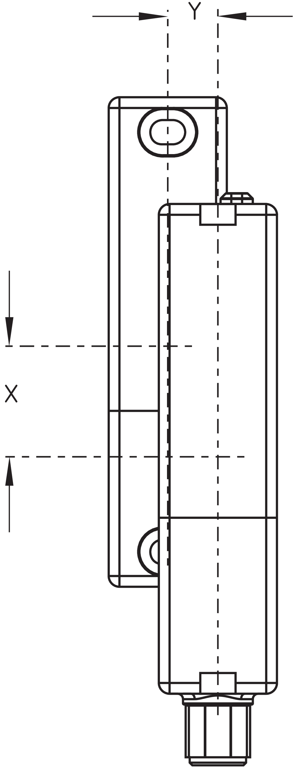
| Note (Repeat accuracy R) |
Axial offset: The long side allows for a maximum height misalignment (x) of sensor and actuator of 8 mm (e.g. mounting tolerance or due to guard door sagging). The axial misalignment (y) is max. ± 18 mm (see figure: Operating principle).Minimum clearance between two sensor systems 100 mm. |
Mechanical data - Connection technique
| Note (length of the sensor chain) |
Cable length and cross-section change the voltage drop dependiing on the output current |
| Note (series-wiring) |
Unlimited number of devices, oberserve external line fusing, max. 31 devices in case of serial diagnostic SD |
| Termination |
Connector M12, 8-pole |
Mechanical data - Dimensions
| Length of sensor |
22 mm |
| Width of sensor |
106.3 mm |
| Height of sensor |
25 mm |
Ambient conditions
| Degree of protection |
IP65 IP67 IP69 |
| Ambient temperature |
-28 ... +70 °C |
| Storage and transport temperature |
-28 ... +85 °C |
| Relative humidity, maximum |
93 % |
| Note (Relative humidity) |
non-condensing non-icing |
| Resistance to vibrations |
10 … 55 Hz, amplitude 1 mm |
| Restistance to shock |
30 g / 11 ms |
| Protection class |
III |
| Permissible installation altitude above sea level, maximum |
2,000 m |
Ambient conditions - Insulation values
| Rated insulation voltage Ui |
32 VDC |
| Rated impulse withstand voltage Uimp |
0.8 kV |
| Overvoltage category |
III |
| Degree of pollution |
3 |
Electrical data
| Operating voltage |
24 VDC -15 % / +10 % (stabilised PELV power supply) |
| Operating current, minimum |
0.5 mA |
| No-load supply current I0, typical |
35 mA |
| Rated operating voltage |
24 VDC |
| Operating current |
600 mA |
| Required rated short-circuit current |
100 A |
| Time to readiness, maximum |
2,000 ms |
| Switching frequency, maximum |
1 Hz |
| Electrical fuse rating, maximum |
2 A |
Electrical data - Safety digital inputs
| Designation, Safety inputs |
X1 and X2 |
| Current consumption of the safety inputs |
5 mA |
| Test pulse duration, maximum |
1 ms |
| Test pulse interval, minimum |
100 ms |
| Classification ZVEI CB24I, Sink |
C1 |
| Classification ZVEI CB24I, Source |
C1 C2 C3 |
Electrical data - Safety digital outputs
| Designation, Safety outputs |
Y1 and Y2 |
| Rated operating current (safety outputs) |
250 mA |
| Output current, (fail-safe output), maximum |
0.25 A |
| Design of control elements |
short-circuit proof, p-type |
| Voltage drop Ud, maximum |
1 V |
| Leakage current Ir, maximum |
0.5 mA |
| Voltage, Utilisation category DC-12 |
24 VDC |
| Current, Utilisation category DC-12 |
0.25 A |
| Voltage, Utilisation category DC-13 |
24 VDC |
| Current, Utilisation category DC-13 |
0.25 A |
| Test pulse interval, typical |
1000 ms |
| Test pulse duration, maximum |
0.3 ms |
| Classification ZVEI CB24I, Source |
C2 |
| Classification ZVEI CB24I, Sink |
C1 C2 |
Electrical data - Diagnostic outputs
| Designation, Diagnostic outputs |
OUT |
| Design of control elements |
short-circuit proof, p-type |
| Voltage drop Ud, maximum |
2 V |
| Voltage, Utilisation category DC-12 |
24 VDC |
| Current, Utilisation category DC-12 |
0.05 A |
| Voltage, Utilisation category DC-13 |
24 VDC |
| Current, Utilisation category DC-13 |
0.05 A |
| Utilisation category DC-12 |
24 VDC / 0.05 A |
Electrical data - Electromagnetic compatibility (EMC)
| Interfering radiation |
IEC 61000-6-4 |
Status indication
| Note (LED switching conditions display) |
LED yellow: Operating condition LED green: Supply voltage LED red: Fault |
Pin assignment
| PIN 1 |
1A1 Ue: (1) |
| PIN 2 |
X1 Safety input 1 |
| PIN 3 |
A2 GND Blue |
| PIN 4 |
Y1 Safety output 1 Black |
| PIN 5 |
OUT Diagnostic output OUT Grey |
| PIN 6 |
X2 Safety input 2 violet |
| PIN 7 |
Y2 Safety output 2 red |
| PIN 8 |
IN without function Pink |
Scope of delivery
| Scope of delivery |
Actuator must be ordered separately. |
Accessory
| Recommendation (actuator) |
RST 36-1 RST 36-1-R |
| Recommended safety switchgear |
PROTECT PSC1 SRB-E-301ST SRB-E-201LC |
Note
| Note (General) |
Teaching of the individual coding of a RST actuator through a simple routine during start-up (as -I1). A protected coding process enables teaching a new actuator in case of maintenance. Anforderungen an die Auswertung: Zweikanaliger Sicherheitseingang, geeignet für p-schaltende Sensoren mit Schließerfunktion. Die Funktionstests der Sensoren mit zyklischem Abschalten der Sensorausgänge für max. 1 ms müssen von der Auswertung toleriert werden. Eine Querschlusserkennung in der Auswertung ist nicht notwendig. |
Language filter
Datasheet
Operating instructions and Declaration of conformity
Operating instructions (supplementary sheet/quick guide)
Declaration of conformity (EC)
UKCA Declaration of Conformity
Info
SISTEMA-VDMA library
Download the latest version of Adobe Reader
Product picture (catalogue individual photo)
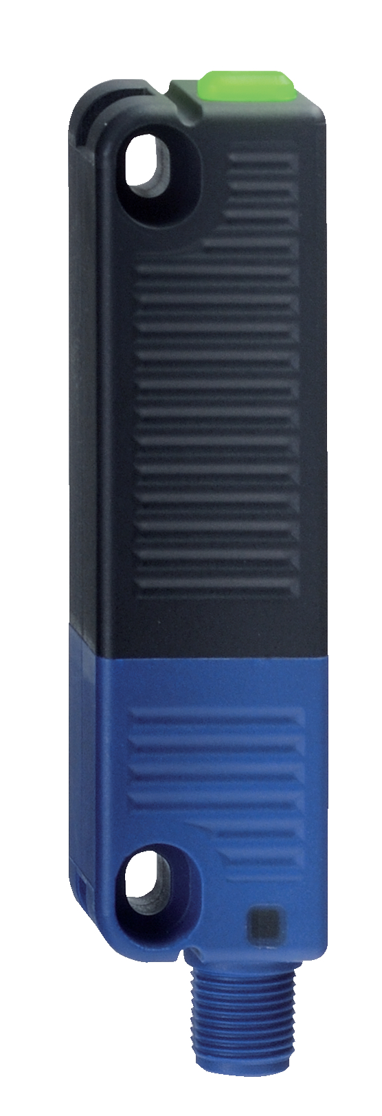
ID: krss3f11
| 501.7 kB | .jpg | 196.144 x 572.9110000000001 mm - 556 x 1624 px - 72 dpi
| 106.3 kB | .png | 74.083 x 216.25300000000001 mm - 210 x 613 px - 72 dpi
| 24.3 kB | .jpg | 42.333000000000006 x 123.47200000000001 mm - 120 x 350 px - 72 dpi
| 23.0 kB | .png | 74.083 x 74.083 mm - 210 x 210 px - 72 dpi
| 8.7 MB | .png | 169.333 x 494.538 mm - 2000 x 5841 px - 300 dpi
Dimensional drawing basic component

Contact arrangement

Operating principle
Video ID: rss-36-01
Basic function (Vimeo)

Video ID: rss-36-02
Variable mounting options (Vimeo)
Video ID: rss-36-03
Single device connection (Vimeo)
Video ID: rss-36-04
Series connection with serial diagnostics (Vimeo)
Video ID: rss-36-05
Cross-fault with controlled shut-down process (Vimeo)
Video ID: rss-36-06
Tolerance to misalignment (Vimeo)
Video ID: rss-36-07
Warning when actuator is in limit range (Vimeo)
Video ID: rss-36-10
Teaching of a replacement actuator to RSS36-I2 (Vimeo)
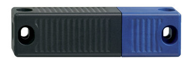
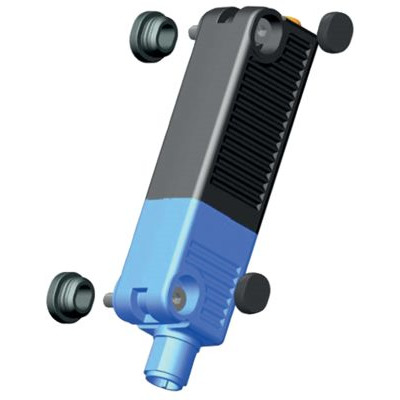
101213820 RST 36-1
- Actuation from side
- Simple flexible mounting and adjustment
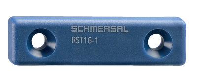
103004336 RST16-1
- Frontal actuation from assembly direction
- Flat design
- Mounting 2 x M5
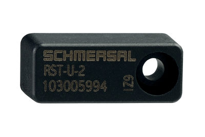
103005994 RST-U-2
- Frontal actuation from assembly direction
- small body
- Mounting 1 x M3 plus Twist protection
101215048 ACC RSS 36-SK
- to seal the mounting holes and as spacer (approx. 3 mm) to facilitate the cleaning below the mounting surface
- also suitable as tampering protection for the screw fixings
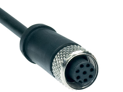
101210560 A-K8P-M12-S-G-5M-BK-1-X-A-4-69-VA
- 5 m
- Pre-wired cable
- 8-pole
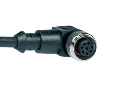
101210561 A-K8P-M12-S-W-5M-BK-1-X-A-4-69-VA
- 5 m
- angled
- Pre-wired cable
- 8-pole
103001389 A-K8P-M12-S-G-10M-BK-1-X-A-4-69-VA
- 10 m
- Pre-wired cable
- 8-pole

103007358 A-K8P-M12-S-G-5M-BK-2-X-A-4-69
- 5 m
- Pre-wired cable
- 8-pole
103007359 A-K8P-M12-S-G-10M-BK-2-X-A-4-69
- 10 m
- Pre-wired cable
- 8-pole

103011411 A-K8P-M12-S-G-2,5M-GY-1-X-A-4
- 2.5 m
- Pre-wired cable
- 8-pole
103011412 A-K8P-M12-S-G-5M-GY-1-X-A-4
- 5.0
- Pre-wired cable
- 8-pole
103011413 A-K8P-M12-S-G-10M-GY-1-X-A-4
- 10 m
- Pre-wired cable
- 8-pole
103011414 A-K8P-M12-S-G-15M-BK-2-X-A-4-69
- 15
- Pre-wired cable
- 8-pole
103011415 A-K8P-M12-S-G-2,5M-BK-2-X-A-4-69
- 2.5 m
- Pre-wired cable
- 8-pole

103011416 A-K8P-M12-S-W-5M-GY-1-X-A-4
- 5 m
- Pre-wired cable
- 8-pole
103014823 A-K8P-M12-S-G-15M-BK-1-X-A-4-69-VA
- 15
- Pre-wired cable
- 8-pole

103043110 A-K8P-M12-S-W-2,5M-BK-2-X-A-4
- angled
- 2.5 m
- Pre-wired cable
- 8-pole
103043119 A-K8P-M12-S-W-5M-BK-2-X-A-4
- angled
- 5 m
- Pre-wired cable
- 8-pole
103043120 A-K8P-M12-S-W-10M-BK-2-X-A-4
- angled
- 10 m
- Pre-wired cable
- 8-pole
103043121 A-K8P-M12-S-W-15M-BK-2-X-A-4
- angled
- 15
- Pre-wired cable
- 8-pole

103009970 SRB-E-201LC
- Plug-in screw terminals with coding
- STOP 0 Function
- 1 oder 2-channel control
- Start button / Auto-start
- 2 Safety outputs 2 A
- 1 Signalling output
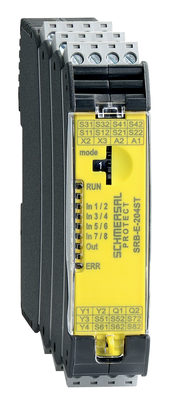
103009973 SRB-E-204ST
- Plug-in screw terminals with coding
- STOP 0 Function
- Monitoring of 4 sensors
- Start button / Auto-start
- 2 Safety outputs
- 4 Signalling outputs

103007672 SRB-E-301ST
- Plug-in screw terminals with coding
- STOP 0 Function
- 1 oder 2-channel control
- Start button / Auto-start
- 1 Auxiliary contact
- 3 safety contacts
Schmersal India Pvt. Ltd., Plot No - G-7/1, Ranjangaon MIDC, Tal. - Shirur, Dist.- Pune 412 220
The details and data referred to have been carefully checked. Images may diverge from original. Further technical data can be found in the manual. Technical amendments and errors possible.
Generated at: 17/04/2026, 11:34 pm