SRB308IT-230VAC
SRB308IT-230VAC
Downloads
- レベル 1: エッジ検出無しリセット, オプション 自動リセット機能, 交差短絡検出, レベル 2: / NC接点 NO接点
- 複数診断・視覚化に対する多機能セーフティリレーユニット
- 非常停止コマンド装置、ポジションスイッチ、セーフティインターロックなどの無電圧接点信号処理に適合
- セーフティライトカーテン・ライトグリッドなどポテンシャルのある信号出力処理に適切
- セーフティ磁気スイッチの出力信号処理に適切
- 3 安全出力, STOP 0
- 2 + 6 補助出力
注文データ
| 注記 (配信容量) |
Not available! |
| 交換品番号 |
101166107 |
| 製品タイプの説明 |
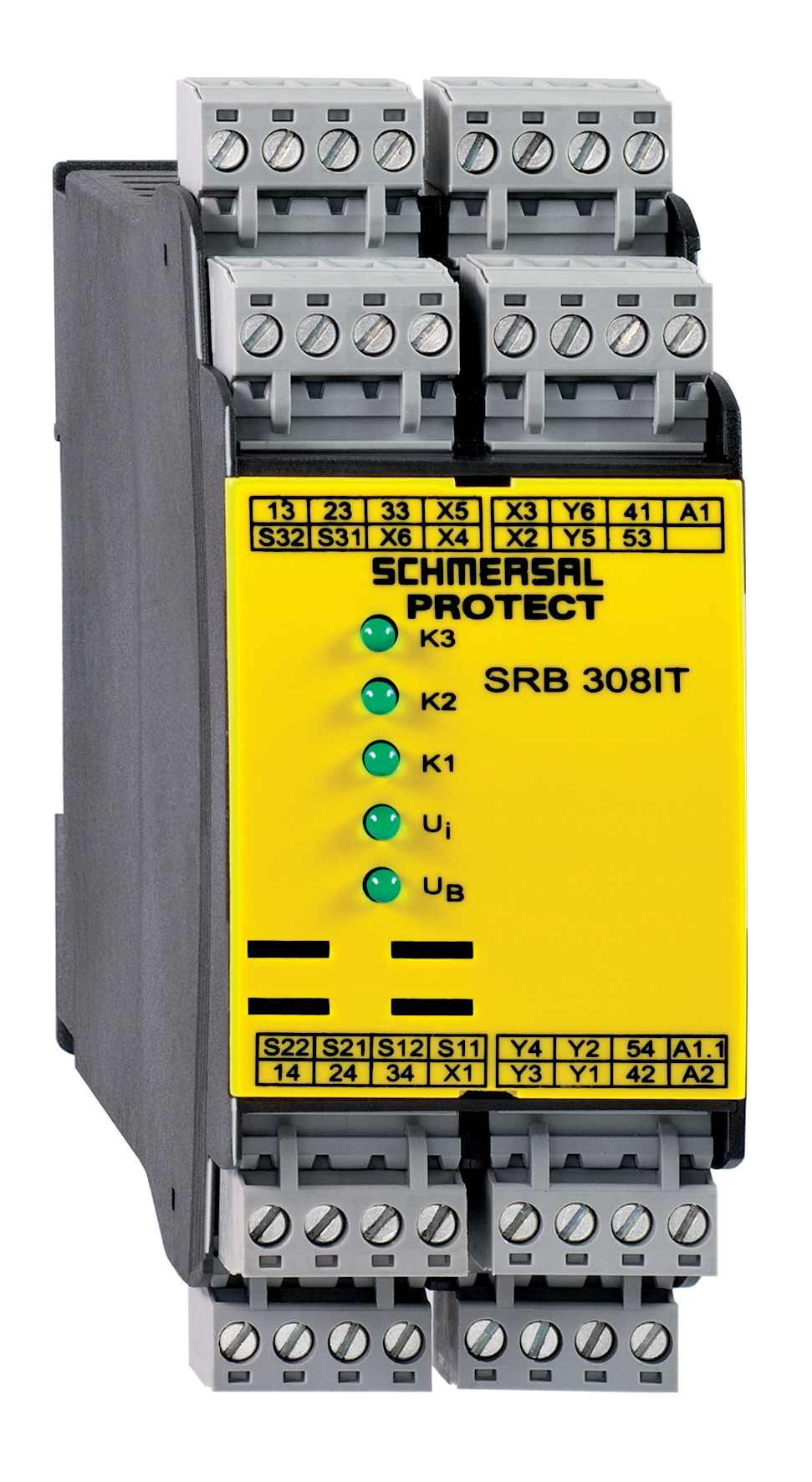
SRB308IT-230VAC |
| 部品番号(注文番号) |
101158202 |
| EAN(欧州部品番号) |
4250116201563 |
| eCl@ss番号、バージョン12.0 |
27-37-18-19 |
| eCl@ss番号、バージョン11.0 |
27-37-18-19 |
| eCl@ss番号、バージョン9.0 |
27-37-18-19 |
| ETIM番号、バージョン7.0 |
EC001449 |
| ETIM番号、バージョン6.0 |
EC001449 |
認証
| 証明書 |
cULus |
一般データ
| 規格 |
EN IEC 62061 EN ISO 13849-1 EN IEC 60947-5-1 EN IEC 60947-5-3 EN IEC 60947-5-5 EN IEC 61508 EN IEC 60204-1 EN IEC 60947-1 |
| 環境ストレス |
EN 60068-2-78 |
| ハウジング 材質 |
グラスファイバー強化熱可塑性樹脂、換気口付き |
| 総重量 |
480 g |
一般データ - 仕様
| 電子ヒューズ |
Yes |
| 断線検出 |
Yes |
| 短絡監視 |
Yes |
| 脱着式端子台 |
Yes |
| スタート入力 |
Yes |
| バックチェック回路 |
Yes |
| 自動リセット機能 |
Yes |
| 立ち下がり検出でリセット |
Yes |
| 地絡検出 |
Yes |
| 一体型システム診断、状態 |
Yes |
| 補助接点数 |
2 |
| LEDの数 |
5 |
| NC接点の数 |
2 |
| 数、信号機能付き遅延のない半導体出力の数 |
6 |
| 安全接点数 |
3 |
| 信号出力数 |
6 |
安全性評価
| 規定 |
EN IEC 60947-5-1 EN IEC 61508 |
| ミッションタイム |
20 年 |
| 共通原因障害(CCF)、最小 |
65 |
| 停止カテゴリー |
0 |
安全性評価 - リレー出力
| パフォーマンスレベル、 Stop 0、 最大 |
e |
| カテゴリー、Stop 0 |
4 |
| 診断カ範囲(DC)レベル、Stop 0 |
≥ 99 % |
| FH値 Stop 0 |
2.00 x 10⁻⁸ /h |
| 安全インテグリティレベル (SIL), Stop 0, 安全度水準に適合 |
3 |
機械的データ
| 機械的寿命、最小 |
10,000,000 操作 |
| 取り付け |
EN 60715に基づくDINレールにワンタッチ取り付け |
機械的データ - 電気機械式
| 配線表示 |
IEC/EN 60947-1 |
| 接続 |
単線 / 撚線 ネジ端子 M20 x 1.5 |
| ケーブル断面積、最小 |
0.25 mm² |
| ケーブル断面積, 最大 |
2.5 mm² |
| クリップの締付トルク |
0.6 Nm |
機械的データ - 寸法
| 幅 |
45 mm |
| 高さ |
100 mm |
| 深さ |
121 mm |
環境条件
| ハウジングの保護等級 |
IP40 |
| 取付領域の保護等級 |
IP54 |
| クリップまたは端子の保護等級 |
IP20 |
| 使用周囲温度 |
-25 ... +45 °C |
| 保管および輸送温度 |
-40 ... +85 °C |
| 耐振動 |
10 ~ 55 Hz、振幅 0.35 mm |
| 耐衝撃 |
30 g / 11 ms |
環境条件 - 絶縁値
| 定格インパルス耐電圧 Uimp |
4 kV |
| 過電圧カテゴリー |
III |
| 汚染度 |
2 |
電気的データ
| 周波数範囲 |
50 Hz 60 Hz |
| 動作電圧 |
230 VAC -15 % / +10 % |
| 定格動作電圧 |
230 VAC |
| 動作電流 |
125 mA |
| 制御用定格AC電圧、50 Hz、最小 |
215 VAC |
| 定格制御電圧 AC 50 Hzにて、最大 |
253 VAC |
| 制御用定格AC電圧、60 Hz、最小 |
215 VAC |
| 定格制御電圧 AC 60 Hzにて、最大 |
253 VAC |
| 使用カテゴリー AC-15 |
230 VAC |
| 使用カテゴリー AC-15 |
1.5 A |
| 使用カテゴリー DC-13 |
24 VDC |
| 使用カテゴリー DC-13 |
1.2 A |
| 消費電力 |
3 W |
| 消費電力 |
3 VA |
| 接点抵抗, 最大 |
0.1 Ω |
| 注意(接点抵抗) |
新しい状態で |
| 「非常停止」時の遮断遅延、最大 |
15 ms |
| 自動リセット時の立ち上がり遅延、通常 |
60 ms |
| リセット時の立ち上がり遅延、通常 |
200 ms |
| 接点材質、電気的 |
AgSn0、Ag-Ni、セルフクリーニング, 強制ガイド式 |
電気的データ - デジタル入力
| 配線抵抗, 最大 |
40 Ω |
電気的データ - 電磁両立性 (EMC)
| EMC定格 |
EMC-Directive |
状態表示
| 表示された操作状況 |
Position relay K2 Position relay K1 Internal operating voltage Ui Position relay K3 |
その他のデータ
| 注意 (アプリケーション) |
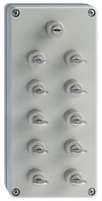
ガードシステム 非常停止ボタン ワイヤーロープ式非常停止スイッチ セーフティライトカーテン |
Note
| 注記 (一般) |
Inductive loads (e.g. contactors, relays, etc.) are to be suppressed by means of a suitable circuit. |
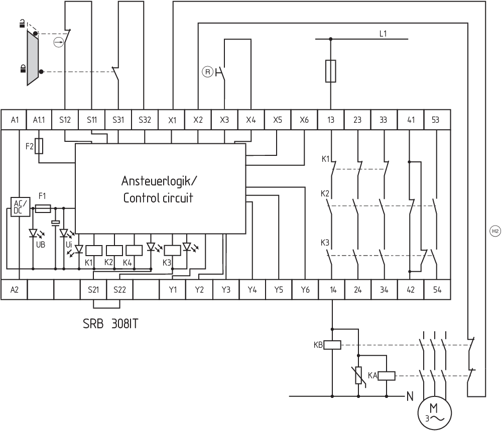
回路例
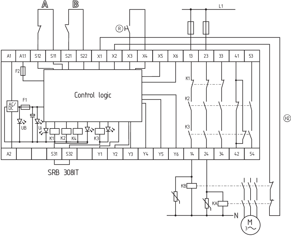
| 注記 (配線図) |
The wiring diagram is shown with guard doors closed and in de-energised condition. The ISD tables (Intergral System Diagnostics) for analysis of the fault indications and their causes are shown in the appendix. Relay outputs: Suitable for 2 channel control, for increase in capacity or number of contacts by means of contactors or relays with positive-guided contacts. The control recognises cross-short, cable break and earth leakages in the monitoring circuit. Connect potential p-type outputs of safety light grids/curtains to S12/S22. The devices must have the same reference potential. 2 channel control shown for a guard-door monitor with two contacts, of which at least one contact has positive break, with external reset button (R) and feedback circuit (H2). (example without cross-wire monitoring) For 2-channel control with cross-wire monitoring, connect the NC contact to S11/S12 and S31/S32 and bridge S21/S22 For 1-channel control, connect NC contact to S11/S12 and bridge S21/S22 and S31/S32 "Start function / Reset button: The function "trailing edge" is programmed by means of the "AF" switch located underneath the housing cover (switch position = 1). The automatic start is programmed by bridging terminals X3/X5 and by switching the "AF" switch to 0. The time offset between the channels is approx. 100 ms. An endless time offset between the channels 1 and 2 is programmed by bridging the terminals X3/X6." F1 = Hybrid fuse F2 = Fuse for signalling outputs |
言語フィルター
データシート
Operating instructions and Declaration of conformity
UL Certificate
Wiring example (electr. wiring)
Force-travel diagram
Adobe Readerの最新版をダウンロードしてください
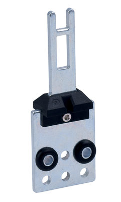
Product picture (catalogue individual photo)
ID: ksrb3f01
| 1,4 MB | .jpg | 342.547 x 625.1220000000001 mm - 971 x 1772 px - 72 dpi
| 100,6 kB | .png | 74.083 x 135.114 mm - 210 x 383 px - 72 dpi
| 63,0 kB | .jpg | 67.733 x 123.47200000000001 mm - 192 x 350 px - 72 dpi
| 45,9 kB | .png | 74.083 x 74.083 mm - 210 x 210 px - 72 dpi
| 9,8 MB | .png | 169.333 x 308.949 mm - 2000 x 3649 px - 300 dpi
Wiring example
Wiring example
Wiring example
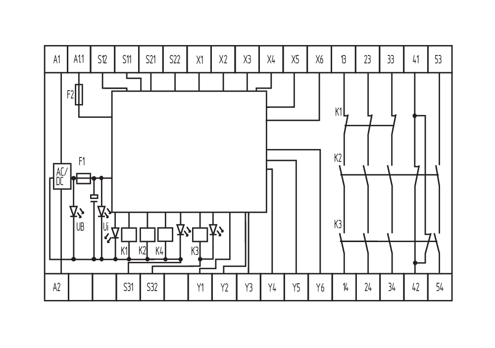
Symbol (technical standard)


103007672 SRB-E-301ST
- STOP 0 機能
- 1 oder 2チャンネルコントロール
- リセットボタン / 自動リセット
- 1 補助接点
- 3 安全出力
シュメアザー株式会社, 〒222-0033 横浜市港北区新横浜3-9-5, 新横浜第3東昇ビル
データと詳細は完全にチェックされました。画像は元の画像と異なる場合があります。技術的なデータはマニュアルで見られます。技術的に変更されたり、エラーの可能性があります。
Generated at: 2026/04/17 18:31
最近見た製品
SHGV/LD1/201/36+BO

HHSNH63-BL-RT