SRB202CS 24VDC
- レベル 1: エッジ検出無しリセット, オプション 自動リセット機能, レベル 2: / NC接点 NC接点
- 組合ユニット(2層式評価)
- 非常停止など異なる遮断動作のある2安全接点は、両安全接点(レベル1)を開きます。また、保護扉監視だけが安全出力2(レベル2)を開きます。
- 非常停止コマンド装置(レベル1)、セーフティポジションスイッチ、セーフティインターロック、非接触式電子セーフティセンサ(レベル2)などの無電圧接点信号処理に適合
- 2 補助出力
注文データ
| 交換品番号 |
101177154 |
| 製品タイプの説明 |
SRB202CS 24VDC |
| 部品番号(注文番号) |
101176208 |
| EAN(欧州部品番号) |
4250116201914 |
| eCl@ss番号、バージョン12.0 |
27-37-18-19 |
| eCl@ss番号、バージョン11.0 |
27-37-18-19 |
| eCl@ss番号、バージョン9.0 |
27-37-18-19 |
| ETIM番号、バージョン7.0 |
EC001449 |
| ETIM番号、バージョン6.0 |
EC001449 |
| 注意 |
生産終了製品 |
認証
| 証明書 |
cULus |
一般データ
| 規格 |
EN IEC 62061 EN ISO 13849-1 EN IEC 60947-5-1 EN IEC 60947-5-3 EN IEC 60947-5-5 EN IEC 61508 EN IEC 60204-1 EN IEC 60947-1 |
| 環境ストレス |
EN 60068-2-78 |
| ハウジング 材質 |
グラスファイバー強化熱可塑性樹脂、換気口付き |
| 総重量 |
235 g |
一般データ - 仕様
| 電子ヒューズ |
Yes |
| 断線検出 |
Yes |
| 脱着式端子台 |
Yes |
| スタート入力 |
Yes |
| バックチェック回路 |
Yes |
| 自動リセット機能 |
Yes |
| 地絡検出 |
Yes |
| 一体型システム診断、状態 |
Yes |
| 補助接点数 |
2 |
| NC用入力の数 |
2 |
| NO用入力の数 |
2 |
| LEDの数 |
6 |
| 安全接点数 |
2 |
安全性評価
| 規定 |
EN IEC 60947-5-1 EN IEC 61508 |
| 停止カテゴリー |
0 |
安全性評価 - リレー出力
| パフォーマンスレベル、 Stop 0、 最大 |
e |
| カテゴリー、Stop 0 |
4 |
| 診断カ範囲(DC)レベル、Stop 0 |
≥ 99 % |
| FH値 Stop 0 |
2.00 x 10⁻⁸ /h |
| 安全インテグリティレベル (SIL), Stop 0, 安全度水準に適合 |
3 |
| ミッションタイム |
20 年 |
| 共通原因障害(CCF)、最小 |
65 |
機械的データ
| 機械的寿命、最小 |
10,000,000 操作 |
| 取り付け |
EN 60715に基づくDINレールにワンタッチ取り付け |
機械的データ - 電気機械式
| 配線表示 |
IEC/EN 60947-1 |
| ケーブル断面積、最小 |
0.25 mm² |
| ケーブル断面積, 最大 |
2.5 mm² |
| クリップの締付トルク |
0.6 Nm |
| 使用可能ケーブル |
ソリッド単線 柔軟な |
| 端子(機械) |
Screw terminals |
機械的データ - 寸法
| 幅 |
22.5 mm |
| 高さ |
100 mm |
| 深さ |
121 mm |
環境条件
| ハウジングの保護等級 |
IP40 |
| 取付領域の保護等級 |
IP54 |
| クリップまたは端子の保護等級 |
IP20 |
| 使用周囲温度 |
-25 ... +45 °C |
| 保管および輸送温度 |
-40 ... +85 °C |
| 耐振動 |
10 ~ 55 Hz、振幅 0.35 mm |
| 耐衝撃 |
10 g / 11 ms |
環境条件 - 絶縁値
| 定格インパルス耐電圧 Uimp |
4 kV |
| 過電圧カテゴリー |
III |
| 汚染度 |
2 |
電気的データ
| 動作電圧 |
24 VDC -10 % / +20 % |
| リップル電圧 |
10 % |
| 定格動作電圧 |
24 VDC |
| DC最小で制御するための定格AC電圧 |
20.4 VDC |
| 定格制御電圧 DCにて、最大 |
28.8 VDC |
| 消費電力 |
4.4 W |
| 接点抵抗, 最大 |
0.1 Ω |
| 注意(接点抵抗) |
新しい状態で |
| 停電時の遮断遅延、通常 |
80 ms |
| 「非常停止」時の遮断遅延、通常 |
20 ms |
| 自動リセット時の立ち上がり遅延、通常 |
100 ms |
| 自動起動時のON遅延 |
Adjustable |
| リセット時の立ち上がり遅延、通常 |
20 ms |
| 接点材質、電気的 |
Ag-Ni, セルフクリーニング, 強制ガイド式 |
電気的データ - 安全リレー出力
| 電圧, 使用カテゴリー AC-15 |
250 VAC |
| 電流、使用カテゴリー AC-15 |
6 A |
| 電圧, 使用カテゴリー DC-13 |
24 VDC |
| 電流、使用カテゴリーDC-13 |
6 A |
| 開閉容量、最小 |
10 VDC |
| 開閉容量、最小 |
10 mA |
| 開閉容量、最大 |
250 VAC |
| 開閉容量、最大 |
8 A |
電気的データ - デジタル入力
| 配線抵抗, 最大 |
40 Ω |
電気的データ - リレー出力 (補助接点)
| 開閉容量、最大 |
24 VDC |
| 開閉容量、最大 |
2 A |
電気的データ - 電磁両立性 (EMC)
| EMC定格 |
EMC-Directive |
状態表示
| 表示された操作状況 |
Position relay K2 Position relay K1 Internal operating voltage Ui Position relay K3 |
その他のデータ
| 注意 (アプリケーション) |
セーフティセンサー ガードシステム 非常停止ボタン ワイヤーロープ式非常停止スイッチ |
Note
| 注記 (一般) |
Inductive loads (e.g. contactors, relays, etc.) are to be suppressed by means of a suitable circuit. |
| 注記 (交差回路検出) |
Level 1 |
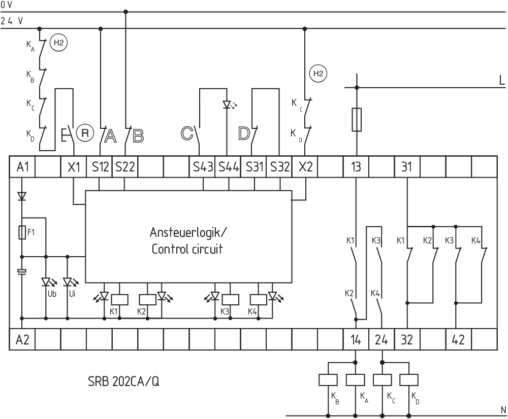
回路例
| 注記 (配線図) |
The wiring diagram is shown with guard doors closed and in de-energised condition. Relay outputs: Suitable for 2 channel control, for increase in capacity or number of contacts by means of contactors or relays with positive-guided contacts. The control recognises cross-short, cable break and earth leakages in the monitoring circuit. Input level: the example shows a 2-channel control of an Emergency Stop command device (level 1) with external reset button (R), and guard door monitoring (level 2) with feedback circuit (H2). Automatic start (level 1): The automatic start is programmed by connecting the feedback circuit to the terminals X1/+24 V DC. Automatic start (level 2): The automatic start is programmed by connecting the feedback circuit to the terminals X2/+24 V DC. If the feedback circuit is not required, establish a bridge. 1 NC contact each time communicates the status of level 1 and level 2 |
言語フィルター
データシート
Operating instructions and Declaration of conformity
UL Certificate
Wiring example (electr. wiring)
SISTEMA-VDMA library
Adobe Readerの最新版をダウンロードしてください
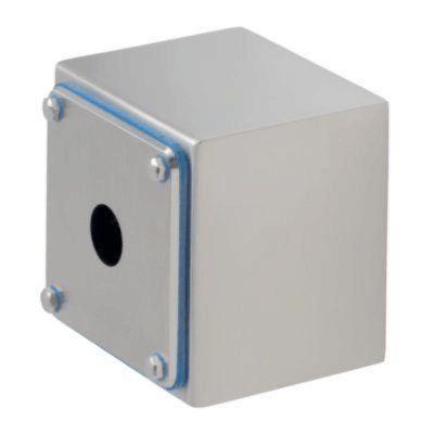
Product picture (catalogue individual photo)

ID: ksrb2f04
| 808,9 kB | .jpg | 265.994 x 625.1220000000001 mm - 754 x 1772 px - 72 dpi
| 100,7 kB | .png | 74.083 x 173.919 mm - 210 x 493 px - 72 dpi
| 39,6 kB | .jpg | 52.564 x 123.47200000000001 mm - 149 x 350 px - 72 dpi
| 29,2 kB | .png | 74.083 x 74.083 mm - 210 x 210 px - 72 dpi
| 8,6 MB | .png | 169.333 x 397.933 mm - 2000 x 4700 px - 300 dpi
Wiring example
Wiring example
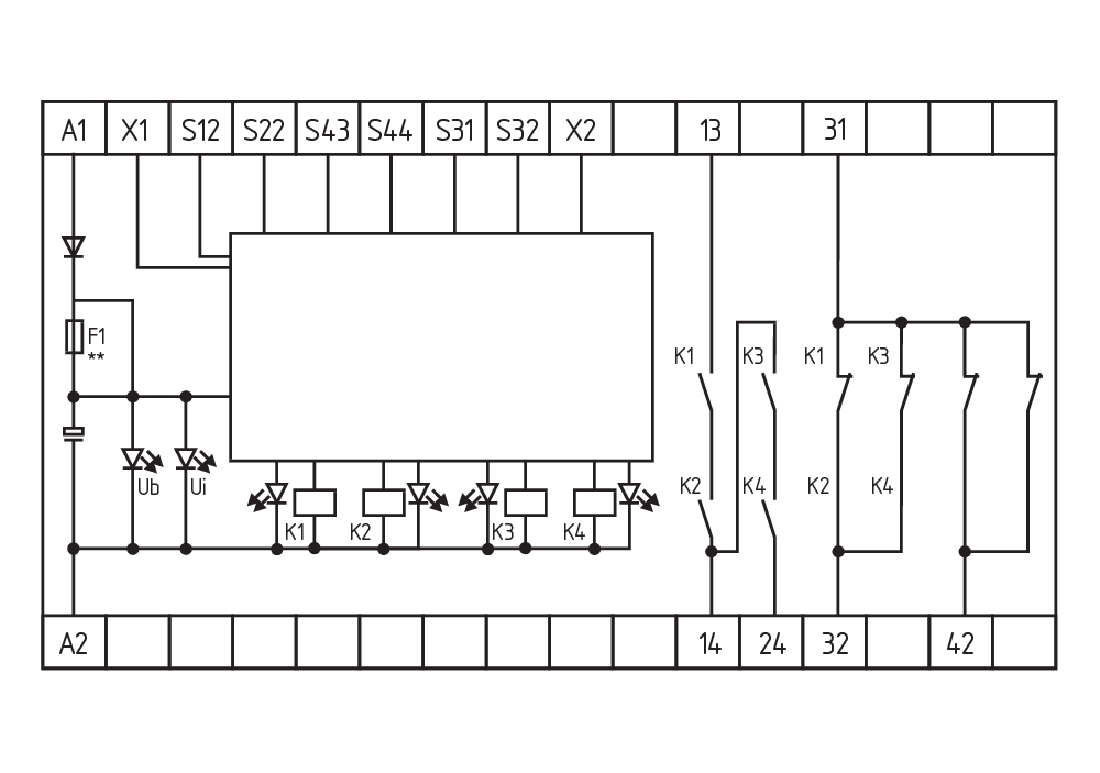
Symbol (technical standard)


103007221 SRB-E-402ST
- 組合ユニット(2層式評価), 2 x STOP 0
- 2 x 1 oder 2チャンネルコントロール
- 2 x リセットボタン / 自動リセット
- 1 x 両手操作パネルの監視(ISO 13851)
- 2 安全出力
- 2 安全出力
| EU Declaration of Conformity |  |
| Original | K.A. Schmersal GmbH & Co. KG Möddinghofe 30 42279 Wuppertal Germany Internet: www.schmersal.com |
| Declaration: | We hereby certify that the hereafter described components both in their basic design and construction conform to the applicable European Directives. |
| Name of the component: | SRB202CS / SRB202CS/T / SRB202CA / SRB202CA/T / SRB202CA/Q / SRB202CA/QT |
| Description of the component: | Safety-monitoring module for emergency stop circuits, guard door monitoring and magnetic safety switches |
| Relevant Directives: | Machinery Directive | 2006/42/EC |
| EMC-Directive | 2014/30/EU | |
| RoHS-Directive | 2011/65/EU |
| Applied standards: | EN 60947-5-1:2004 + AC:2005 + A1:2009 EN 60947-5-1:2017 EN ISO 13850:2015 EN ISO 13849-1:2015 EN ISO 13849-2:2012 EN 61326-3-1:2017 |
| Notified body, which approved the full quality assurance system, referred to in Appendix X, 2006/42/EC: | TÜV Rheinland Industrie Service GmbH Am Grauen Stein, 51105 Köln ID n°: 0035 |
| Person authorised for the compilation of the technical documentation: | Oliver Wacker Möddinghofe 30 42279 Wuppertal |
| Place and date of issue: | Wuppertal, November 22, 2021 |
 |
| Authorised signature Philip Schmersal Managing Director |
シュメアザー株式会社, 〒222-0033 横浜市港北区新横浜3-9-5, 新横浜第3東昇ビル
データと詳細は完全にチェックされました。画像は元の画像と異なる場合があります。技術的なデータはマニュアルで見られます。技術的に変更されたり、エラーの可能性があります。
Generated at: 2026/04/15 7:12
最近見た製品

TESZR110

SSW303HV
SHGV/R01/111+BO

PWR-5M-SET

NZSO-V4A