EX-ZQ 900-11-3D
| Product type description: EX-ZQ 900 -(1)-3D |
| (1) | |
| 11 | 1 NO contact/1 NC contact |
| 13 | 1 NO contacts/3 NC contact |
| 22 | 2 NO contacts/2 NC contact |
| 02 | 2 NC contact |
| 04 | 4 NC contact |
- 3 cable entries M 20 x 1.5
- Ex-Zone 22
- Metal enclosure
- Release push button
- Position indicator
- Robust design
- Large wiring compartment
- Twisting of towing eye not possible
- External watertight collar
- wire pull and breakage detection
- one-side operation / wire up to 75 m long
Ordering data
| Product type description |
EX-ZQ 900-11-3D |
| Article number (order number) |
101212889 |
| EAN (European Article Number) |
4030661402215 |
| eCl@ss number, version 12.0 |
27-37-12-01 |
| eCl@ss number, version 11.0 |
27-37-12-01 |
| eCl@ss number, version 9.0 |
27-37-12-01 |
| ETIM number, version 7.0 |
EC002033 |
| ETIM number, version 6.0 |
EC002033 |
Approvals - Standards
| Certificates |
ATEX (Konformitätserklärung) |
Explosion protection
| Explosion protection: regulations |
EN IEC 60079-0 EN 60079-31 |
| Explosion protection zones |
22 |
| Explosion protection category |
3D |
| Explosion protection designation |
D II 3D Ex tc IIIC T100°C Dc |
General data
| Standards |
EN ISO 13850 EN IEC 60947-5-1 EN IEC 60947-5-5 |
| Housing material |
Metal, zinc die-cast |
| Housing coating material |
painted |
| Material of the housing cover |
Steel |
| Length of the wire, maximum |
75 m |
| Gross weight |
1,600 g |
General data - Features
| Number of auxiliary contacts |
1 |
| Number of safety contacts |
1 |
Safety classification
| Standards |
EN ISO 13849-1 |
| Mission time |
20 Year(s) |
Safety classification - Safety outputs
| B10D Normally-closed contact (NC) |
100,000 Operations |
Mechanical data
| Mechanical lifetime, minimum |
1,000,000 Operations |
| Actuating force, maximum |
200 N |
| Actuation direction |
One-side operation |
| Actuating travel |
400 mm |
Mechanical data - Connection technique
| Termination |
Screw terminals M20 x 1.5 |
| Cable cross-section of the cable glands, minimum |
7 mm |
| Cable cross-section of the cable glands, maximum |
12 mm |
| Cable section, minimum |
0.75 mm² |
| Cable section, maximum |
2.5 mm² |
| Note |
All indications including the conductor ferrules. |
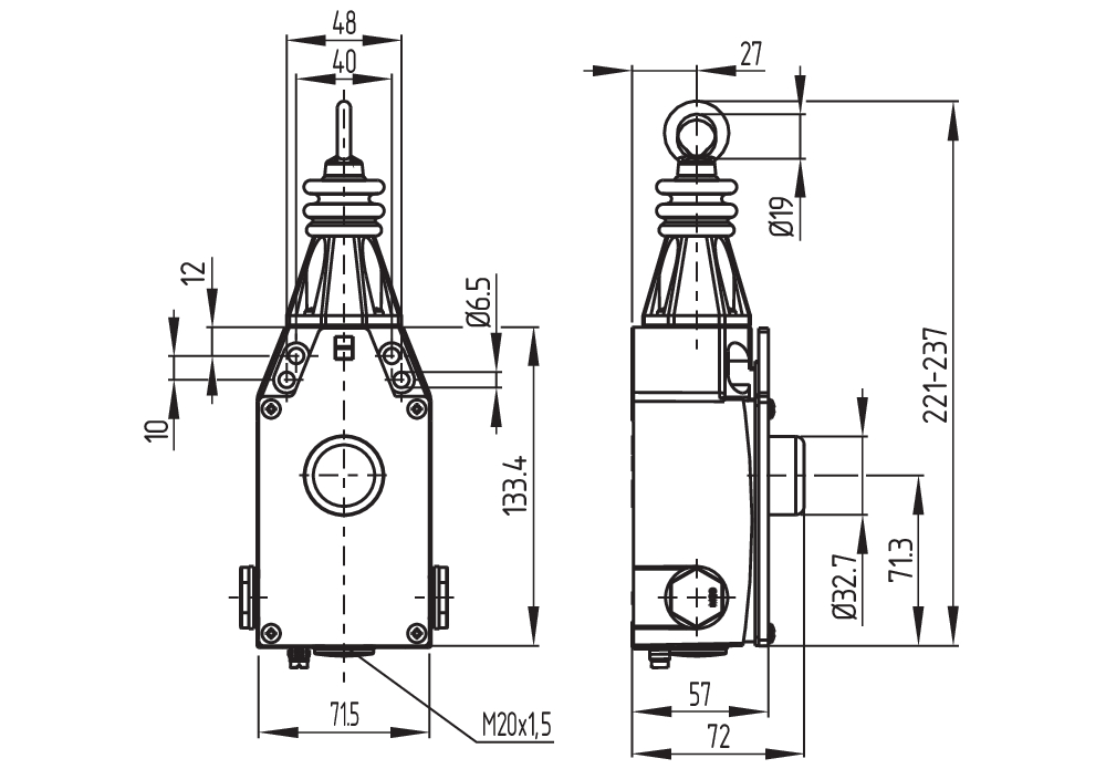
Mechanical data - Dimensions
| Length of sensor |
57 mm |
| Width of sensor |
71.5 mm |
| Height of the Sensor, minimum |
221 mm |
| Height of the Sensor, maximum |
237 mm |
Ambient conditions
| Degree of protection |
IP67 |
| Ambient temperature |
-20 ... +55 °C |
| Relative humidity, minimum |
30 % |
| Relative humidity, maximum |
95 % |
Ambient conditions - Insulation values
| Rated insulation voltage Ui |
500 V |
| Rated impulse withstand voltage Uimp |
6 kV |
Electrical data
| Thermal test current |
4 A |
| Utilisation category AC-15 |
230 VAC |
| Utilisation category AC-15 |
4 A |
| Utilisation category DC-13 |
24 VDC |
| Utilisation category DC-13 |
1 A |
| Switching element |
NO contact, NC contact |
| Switching principle |
Snap action |
| Material of the contacts, electrical |
Silver |
Scope of delivery
| Scope of delivery |
Including Ex-certified screwed cable gland and screw plug |
Note
| Note (General) |
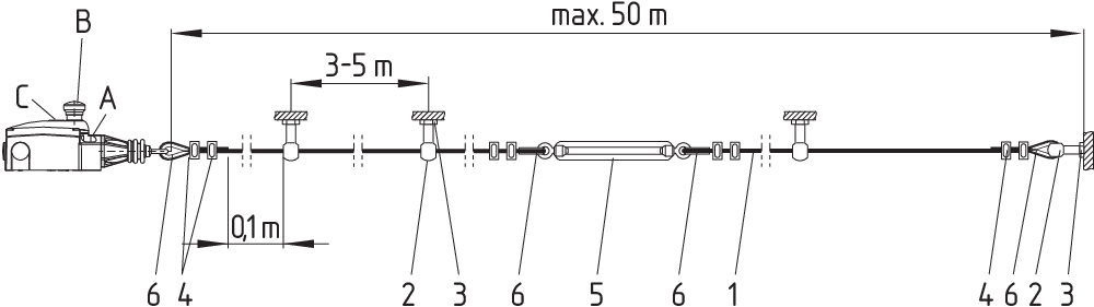
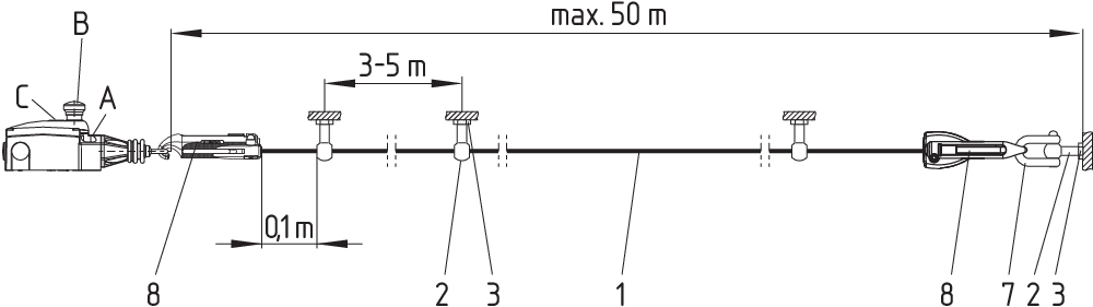
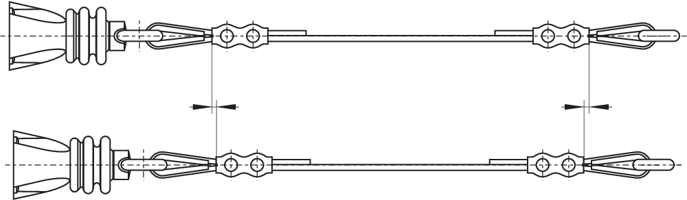
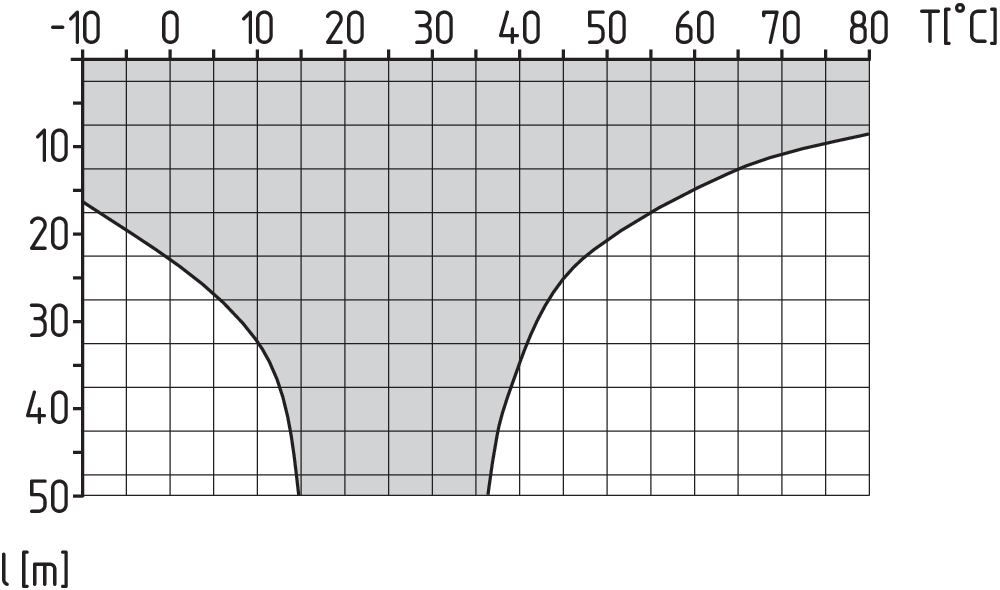
For lengths of over 10 m, intermediate wire supports must be installed every 3 to 5 m. Recommended cable lengths for pull-wire Emergency-Stop switches in relation to the range of ambient temperature. As the thimbles are subject to deformation in case of wire pull, the wire should be pulled several times after fitting. After that, the wire must be re-tensioned using the eyebolt or the tensioner. |
Language filter
Datasheet
Operating instructions and Declaration of conformity
SISTEMA-VDMA library
Download the latest version of Adobe Reader
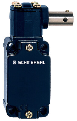
Product picture (catalogue individual photo)
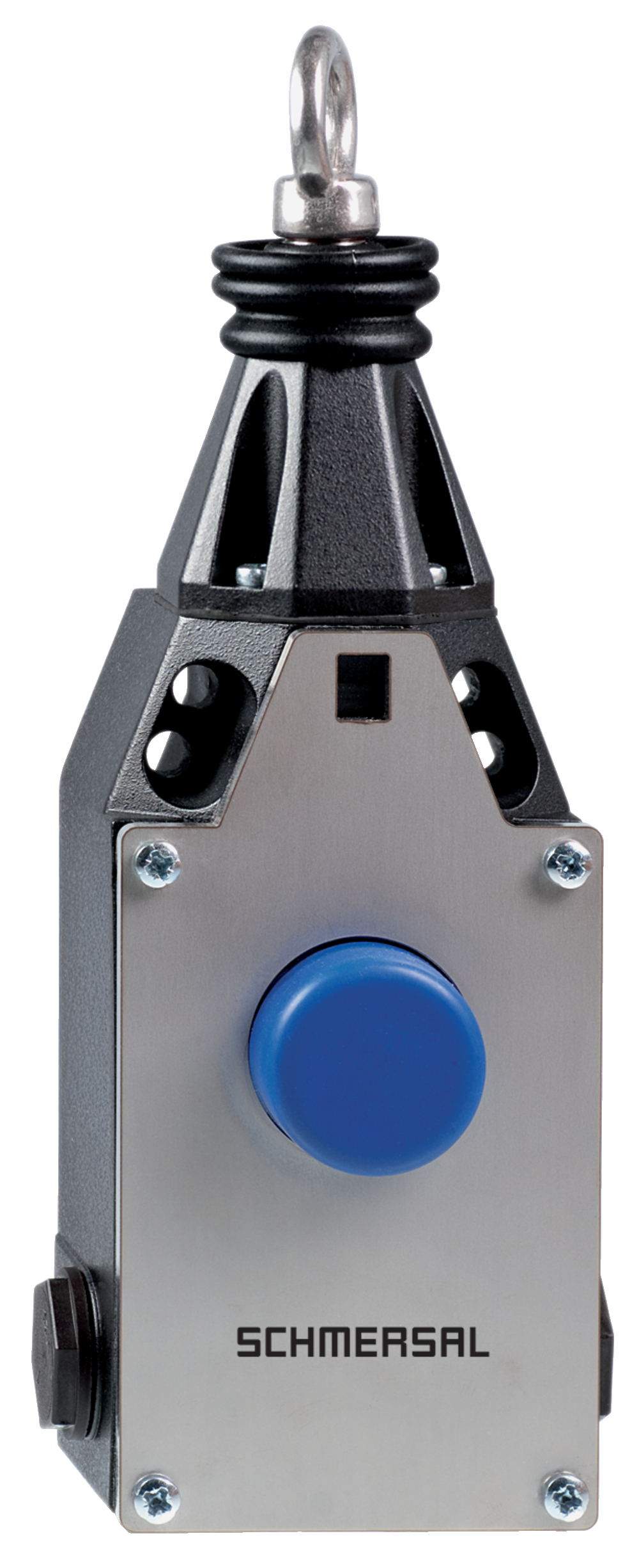
ID: kxzq9f01
| 817.8 kB | .jpg | 352.778 x 864.306 mm - 1000 x 2450 px - 72 dpi
| 138.1 kB | .png | 74.083 x 181.328 mm - 210 x 514 px - 72 dpi
| 27.2 kB | .png | 74.083 x 74.083 mm - 210 x 210 px - 72 dpi
| 51.0 kB | .jpg | 172.86100000000002 x 423.333 mm - 490 x 1200 px - 72 dpi
| 8.6 MB | .png | 169.333 x 414.951 mm - 2000 x 4901 px - 300 dpi
| 27.4 kB | .jpg | 50.447 x 123.47200000000001 mm - 143 x 350 px - 72 dpi
Dimensional drawing basic component
Diagram
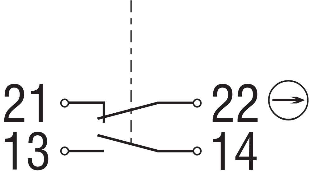
Operating principle
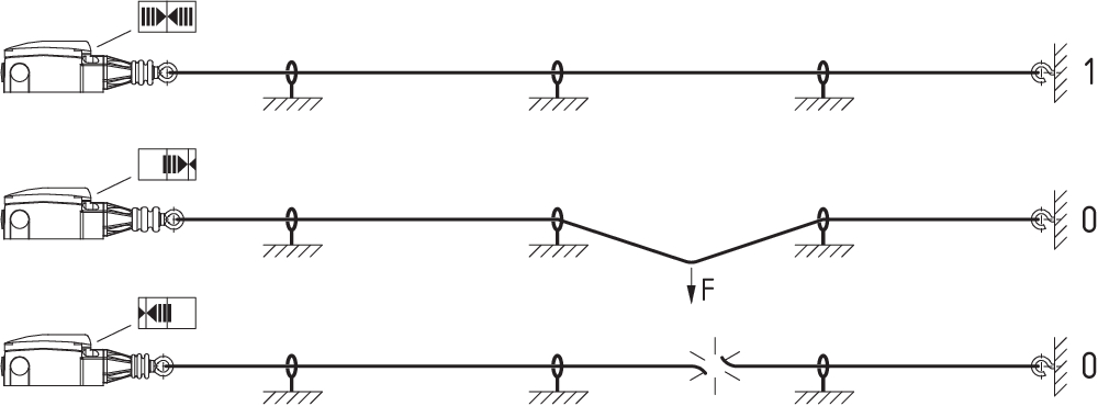
Operating principle
Operating principle
Operating principle
Characteristic curve


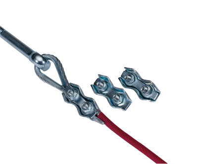
101190917 DUPLEX WIRE CLAMP 3 MM (STAINLESS STEEL)
- for Wire rope Ø 3 mm

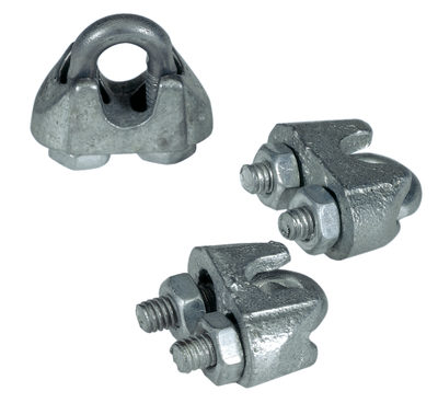
101196043 WIRE CLAMP SZ. 3 EGG-SHAPED OFFS.
- for Wire rope Ø 3 mm

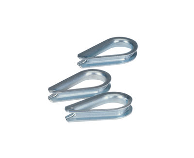
101203472 ACC-PWR-WT-3MM-NIRO
- for Wire rope Ø 3 mm
101203476 ACC-PWR-WT-5MM-NIRO
- for Wire rope Ø 5 mm

101192433 ACC-PWR-PLY-S
- To guide the wire rope where the path is not a straight line
- for Wire rope Ø 5 mm
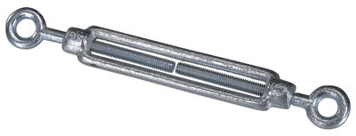
101087930 ACC-PWR-TB-M6-2
- For exact adjustment of the tension of the wire rope
- to DIN 1480
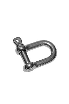
101186490 ACC-PWR-SKL-A0,16-VA
- Shackle for fixing the wire rope to the eyebolt

103003628 PWR-5M-SET
- With red PVC sheath
- Ready-to-fit
103003629 PWR-10M-SET
- With red PVC sheath
- Ready-to-fit
103003865 PWR-15M-SET
- With red PVC sheath
- Ready-to-fit
103003866 PWR-20M-SET
- With red PVC sheath
- Ready-to-fit
103003630 PWR-30M-SET
- With red PVC sheath
- Ready-to-fit
103003867 PWR-40M-SET
- With red PVC sheath
- Ready-to-fit
103003631 PWR-50M-SET
- With red PVC sheath
- Ready-to-fit
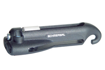
101186704 S 900
- Smooth adjustment
- Only one tool
- Antiskid
- Time-saving
- Ergonomic
- No risk of injury

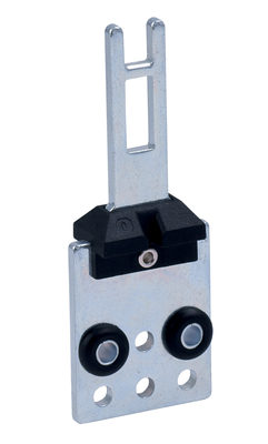
101193805 MOUNTING PLATE SET Z/TQ900 -441/75
- Mounting plate set for ZQ 900 / TQ 900
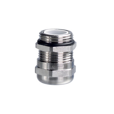
103006011 ACC-CGLD-M20-MS
- cable gland M20
- Metal film
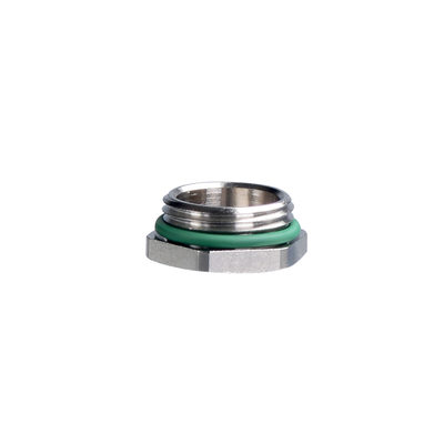
103006009 ACC-BPL-M20-MS
- Locking screw M20
- Metal film

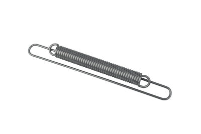
103033772 ACC-RS900-TS
- To maintain the reaction force
| EU Declaration of Conformity |  |
| Original | K.A. Schmersal GmbH & Co. KG Möddinghofe 30 42279 Wuppertal Germany Internet: www.schmersal.com |
| Declaration: | We hereby certify that the hereafter described components both in their basic design and construction conform to the applicable European Directives. |
| Name of the component: | EX-ZQ 900-...-3D |
| Type: | See ordering code |
| Marking: | D II 3D Ex tc IIIC T100°C Dc |
| Description of the component: | Pull-wire emergency stop switch with safety function |
| Relevant Directives: | Machinery Directive | 2006/42/EC |
| Explosion Protection Directive (ATEX) | 2014/34/EU | |
| RoHS-Directive | 2011/65/EU |
| Applied standards: | EN 60947-5-1:2017 + AC:2020 EN 60947-5-5:1997 + A1:2005 + A11:2013 + A2:2017 EN 620:2021 EN ISO 13850:2015 EN IEC 60079-0:2018 + AC:2020 EN 60079-31:2014 |
| Person authorised for the compilation of the technical documentation: | Oliver Wacker Möddinghofe 30 42279 Wuppertal |
| Conformity with the explosion protection directive 2014/34/EU (ATEX) is declared by the manufacturer without involving a test center. |
| Place and date of issue: | Wuppertal, March 31, 2025 |
 |
| Authorised signature Philip Schmersal Managing Director |
K.A. Schmersal GmbH & Co. KG, Möddinghofe 30, 42279 Wuppertal
The details and data referred to have been carefully checked. Images may diverge from original. Further technical data can be found in the manual. Technical amendments and errors possible.
Generated at: 17/04/2026, 19:01
Recently viewed

T4V10H 335-02ZH

ACC-AZM40-ADJ-1
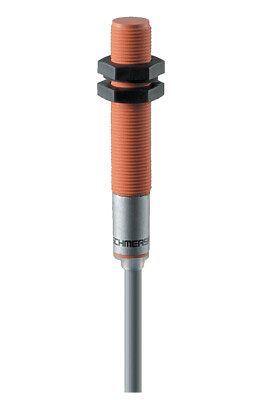
IFL 4-120-10 5,0M
SHGV/RD1/207/33+BO

M4VH 336-20Z-M20
AZM150SK-11/11RA-024