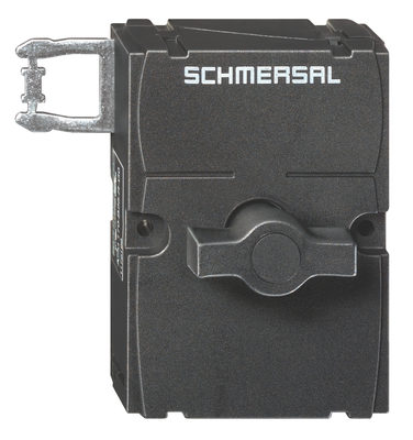
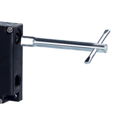
AZM 170ST-02/01ZRKA-24VAC/DC
AZM 170ST-02/01ZRKA-24VAC/DC
| Product type description: AZM 170(1)-(2)Z(3)K(4)-(5)-(6)-(7)-(8) |
| (1) | |
| Cut clamps | |
| SK | Screw connection |
| (2) | |
| 11 | 1 NO contact/1 NC contact |
| 02 | 2 NC contact |
| (3) | |
| Latching force 5 N | |
| R | Latching force 30 N |
| (4) | |
| Power to unlock | |
| A | Power to lock |
| (5) | |
| Cable entry M20 | |
| ST | 2 connector, M12, 4-pin |
| ST-2431 | As per the ST with additional individual solenoid monitoring |
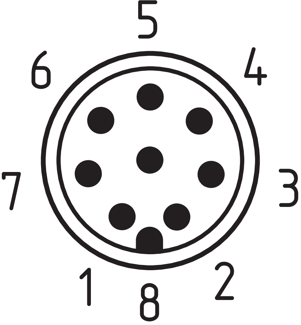
| ST8 | Connector M12 8-pole |
| (6) | |
| 24 VAC/DC | Us 24 VAC/DC |
| 110 VAC | Us 110 VAC |
| 230 VAC | Us 230 VAC |
| (7) | |
| 1637 | Gold-plated contacts |
| (8) | |
| Manual release | |
| 2197 | Manual release from side (default in the power-to-unlock version) |
| 2405 | Emergency exit from side |
- Thermoplastic enclosure
- Double-insulated
- Compact design
- Interlock with protection against incorrect locking.
- Long life
- High holding force
Ordering data
| Product type description |
AZM 170ST-02/01ZRKA-24VAC/DC |
| Article number (order number) |
103059606 |
| EAN (European Article Number) |
4030661665146 |
| eCl@ss number, version 12.0 |
27-27-26-03 |
| eCl@ss number, version 11.0 |
27-27-26-03 |
| eCl@ss number, version 9.0 |
27-27-26-03 |
| ETIM number, version 7.0 |
EC002593 |
| ETIM number, version 6.0 |
EC002593 |
General data
| Standards |
EN ISO 13849-1 EN ISO 14119 EN IEC 60947-5-1 |
| Coding level according to EN ISO 14119 |
Low |
| Working principle |
electromechanical |
| Housing material |
Plastic, glass-fibre reinforced thermoplastic, self-extinguishing |
| Gross weight |
334 g |
General data - Features
| Power to lock |
Yes |
| Increased latching force |
Yes |
| Number of actuating directions |
2 |
| Number of safety contacts |
3 |
Safety classification
| Standards |
EN ISO 13849-1 |
| Performance Level, up to |
c |
| Category |
1 |
| B10D Normally-closed contact (NC) |
2,000,000 Operations |
| Note |
Electrical life on request. |
| B10D Normally-open contact (NO) |
1,000,000 Operations |
| Note |
at 10% Ie and ohmic load |
| Mission time |
20 Year(s) |
Safety classification - Fault exclusion
| Please note: |
Can be used when fault exclusion for dangerous damage to the 1-channel mechanism is permissible and sufficient protection against manipulation is guaranteed. |
| Performance Level, up to |
d |
| Category |
3 |
| Note |
for 2-channel use and with suitable logic unit. |
| Mission time |
20 Year(s) |
Mechanical data
| Mechanical lifetime, minimum |
1,000,000 Operations |
| Holding force FZh in accordance with EN ISO 14119 |
1,000 N |
| Holding force Fmax, maximum |
1,300 N |
| Latching force |
30 N |
| Positive break travel |
11 mm |
| Positive break force per NC contact, minimum |
8.5 N |
| Actuating speed, maximum |
2 m/s |
| Mounting |
Screws |
| Type of the fixing screws |
2x M4 |
| Tightening torque of the fastening screws for the housing cover, minimum |
0.7 Nm |
| Tightening torque of the fastening screws for the housing cover, maximum |
1 Nm |
| Note |
Torx T10 |
Mechanical data - Connection technique
| Terminal (mechanical) |
Connector plug M12, 8-pole, A-coded |
Mechanical data - Dimensions
| Length of sensor |
30 mm |
| Width of sensor |
90 mm |
| Height of sensor |
92.5 mm |
Ambient conditions
| IP Degree of protection |
IP67 |
| Note (Relative humidity) |
non-condensing non-icing |
| Protection class |
II |
| Permissible installation altitude above sea level, maximum |
2,000 m |
Ambient conditions - Insulation values
| Rated insulation voltage Ui |
60 V |
| Rated impulse withstand voltage Uimp |
0.8 kV |
| Overvoltage category |
III |
| Degree of pollution |
3 |
Electrical data
| Thermal test current |
2 A |
| Rated control voltage |
24 VDC |
| Rated operating voltage |
24 VDC |
| Operating current |
2,000 mA |
| Required rated short-circuit current |
1,000 A |
| Electrical power consumption, maximum |
12 W |
| Switching element |
Magnet: 2 NC contacts / Actuator: 1 NC contact |
| Note (Switching element) |
Change-over contact with double break, type Zb or 2 NC contacts, with galvanically separated contact bridges |
| Switching principle |
slow action, positive break NC contact |
| Maximale Schalthäufigkeit |
1,000 /h |
| Material of the contacts, electrical |
Silver |
Electrical data - Magnet control
| Magnet switch-on time |
100 % |
| Test pulse duration, maximum |
5 ms |
| Test pulse interval, minimum |
50 ms |
Electrical data - Safety contacts
| Voltage, Utilisation category DC-13 |
24 VDC |
| Current, Utilisation category DC-13 |
2 A |
Electrical data - Auxiliary contacts
| Voltage, Utilisation category DC-13 |
24 VDC |
| Current, Utilisation category DC-13 |
2 A |
Other data
| Note (applications) |
sliding safety guard removable guard hinged safety guard |
Scope of delivery
| Scope of delivery |
Actuator must be ordered separately. Slot sealing plugs |
Language filter
Datasheet
SISTEMA-VDMA library
Download the latest version of Adobe Reader
Product picture (catalogue individual photo)
ID: kazm1f85
| 450.7 kB | .jpg | 352.778 x 325.261 mm - 1000 x 922 px - 72 dpi
| 47.8 kB | .png | 74.083 x 68.43900000000001 mm - 210 x 194 px - 72 dpi
| 45.8 kB | .png | 74.083 x 74.083 mm - 210 x 210 px - 72 dpi
| 4.5 MB | .png | 169.333 x 156.041 mm - 2000 x 1843 px - 300 dpi
| 54.6 kB | .jpg | 123.47200000000001 x 113.947 mm - 350 x 323 px - 72 dpi
Switch travel diagram
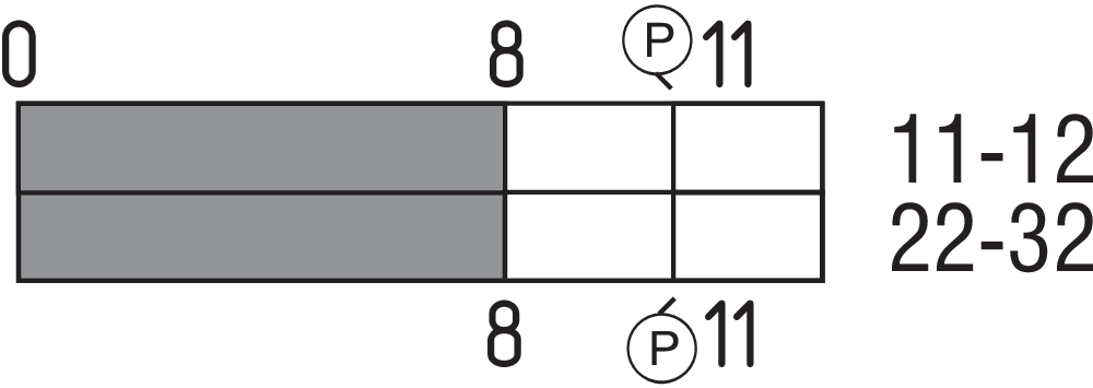
Diagram

Contact arrangement

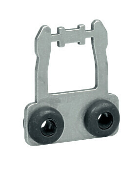
101122893 ACTUATOR AZ 17/170-B1
- Particularly suitable for sliding doors
- Straight actuator
- Particularly suitable for sliding doors
101137406 ACTUATOR AZ 17/170-B1-2245
- Straight actuator with rubber mounting
- Damps vibration on guard device
- Particularly suitable for sliding doors

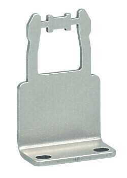
101122895 ACTUATOR AZ 17/170-B5
- Particularly suitable for sliding doors
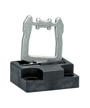
101123391 ACTUATOR AZM 170-B6
- Particularly suitable for hinged guards
- The direction of actuation can be selected by applicable insertion of the insert

101139788 ACTUATOR AZ 17/170-B11
- Particularly suitable for sliding doors
101139789 ACTUATOR AZ 17/170-B15
- Particularly suitable for sliding doors
- Particularly suitable for sliding doors

101175201 ACTUATOR AZM 170-B25-L-G1
- Door hinge on left-hand side (View point towards the hazardous area)
- with Star grip
- Ergonomic operation
- No supplementary door-handle required
- No protruding actuator
- Simple mounting
- Several door-handles available
- Possibility to mount the own handles using a default square screw (8 mm)
101175227 ACTUATOR AZM 170-B25-L-G2
- Door hinge on left-hand side (View point towards the hazardous area)
- with T-grip
- Ergonomic operation
- No supplementary door-handle required
- No protruding actuator
- Simple mounting
- Several door-handles available
- Possibility to mount the own handles using a default square screw (8 mm)
101175200 ACTUATOR AZM 170-B25-R-G1
- Door hinge on right-hand side (View point towards the hazardous area)
- with Star grip
- Ergonomic operation
- No supplementary door-handle required
- No protruding actuator
- Simple mounting
- Several door-handles available
- Possibility to mount the own handles using a default square screw (8 mm)

101175226 ACTUATOR AZM 170-B25-R-G2
- Door hinge on right-hand side (View point towards the hazardous area)
- with T-grip
- Ergonomic operation
- No supplementary door-handle required
- No protruding actuator
- Simple mounting
- Several door-handles available
- Possibility to mount the own handles using a default square screw (8 mm)
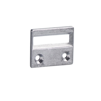
101208493 AZM 170-B ZENTRIERHILFE
- for AZ 17 and AZM 170
101100887 TK-M5
- For manual release using M5 triangular key, available as accessory
- For maintenance, installation, etc.


K.A. Schmersal GmbH & Co. KG, Möddinghofe 30, 42279 Wuppertal
The details and data referred to have been carefully checked. Images may diverge from original. Further technical data can be found in the manual. Technical amendments and errors possible.
Generated at: 27/04/2026, 19:03
Recently viewed

SLC 220-E/R0175-30-69-RFB-H

T3K 236-11Z-M16-1894

BNS 303-12Z-2187/2211 10,0M

ZV14H 236-11Z-U90-1853
BDF200-NH-10-LTBU-LTGN-LTRD-G24
G150-100M44/M44Y-5025