AZR31T0/24VDC/AC
- Fail-safe standstill monitors
- Sensor-free detection of standstill by monitoring e.m.f.
- Direct connection to three-phase motors
- Suitable for connection to a frequency converter with the following interface date: rotary hysteresis 0 ... 1000 Hz; switching frequency of the end level up to 16 kHz; engine voltage range 0 ... 400 V
- This fail-safe standstill monitor has the particular advantage that no adjustment for a required-value is needed during comissioning.
- 3 safety contacts, STOP 0
- 1 Signalling output
Ordering data
| Product type description |
AZR31T0/24VDC/AC |
| Article number (order number) |
101049653 |
| EAN (European Article Number) |
4030661521268 |
General data
| Standards |
EN IEC 62061 EN ISO 13849-1 EN IEC 60947-5-1 EN IEC 60947-5-3 EN IEC 60947-5-5 EN IEC 61508 EN IEC 60204-1 EN IEC 60947-1 |
| Climatic stress |
EN 60068-2-78 |
| Housing material |
Glass-fibre, reinforced thermoplastic |
| Gross weight |
250 g |
General data - Features
| Wire breakage detection |
Yes |
| Cross-circuit detection |
Yes |
| Feedback circuit |
Yes |
| Automatic reset function |
Yes |
| Earth connection detection |
Yes |
| Integral system diagnostics, status |
Yes |
| Number of auxiliary contacts |
1 |
| Number of LEDs |
5 |
| Number of safety contacts |
3 |
Safety classification
| Standards |
EN IEC 60947-5-1 EN IEC 61508 |
| PFH value |
2.00 x 10⁻⁸ /h |
| Mission time |
20 Year(s) |
| Common Cause Failure (CCF), minimum |
65 |
| Stop-Category |
0 |
Safety classification - Relay outputs
| Performance Level, stop 0, up to |
e |
| Category, Stop 0 |
4 |
| Diagnostic Coverage (DC) Level, Stop 0 |
≥ 99 % |
| Safety Integrity Level (SIL), Stop 0, suitable for applications in |
3 |
Mechanical data
| Mechanical lifetime, minimum |
10,000,000 Operations |
| Mounting |
Snaps onto standard DIN rail to EN 60715 |
Mechanical data - Connection technique
| Terminal designations |
IEC/EN 60947-1 |
| Termination |
rigid or flexible Screw terminals M20 x 1.5 |
| Cable section, minimum |
0.25 mm² |
| Cable section, maximum |
2.5 mm² |
| Tightening torque of Clips |
0.6 Nm |
Mechanical data - Dimensions
| Width |
45 mm |
| Height |
73.2 mm |
| Depth |
121 mm |
Ambient conditions
| Degree of protection of the enclosure |
IP40 |
| Degree of protection of the installation space |
IP54 |
| Degree of protection of clips or terminals |
IP20 |
| Ambient temperature |
-25 ... +45 °C |
| Resistance to vibrations |
10 ... 55 Hz, Amplitude 0.35 mm |
| Restistance to shock |
30 g / 11 ms |
Ambient conditions - Insulation values
| Rated impulse withstand voltage Uimp |
4 kV |
| Overvoltage category |
III |
| Degree of pollution |
2 |
Electrical data
| Frequency range |
50 Hz 60 Hz |
| Contact resistance, maximum |
0.1 Ω |
| Note (Contact resistance) |
in new state |
| Cable length (Master/Slave), maximum |
10 m |
| Drop-out delay in case of power failure, typically |
80 ms |
| Drop-out delay in case of emergency, typically |
20 ms |
| Drop-out delay in case of "emergency stop", maximum |
15 ms |
| Pull-in delay at automatic start (after detecting standstill), approx. |
7,000 ms |
| Pull-in delay at RESET, typically |
20 ms |
| Material of the contacts, electrical |
AgSn0. self-cleaning, positive drive |
Electrical data - Safe relay outputs
| Voltage, Utilisation category AC-15 |
230 VAC |
| Current, Utilisation category AC-15 |
6 A |
| Voltage, Utilisation category DC-13 |
24 VDC |
| Current, Utilisation category DC-13 |
6 A |
| Switching capacity, minimum |
10 VDC |
| Switching capacity, minimum |
10 mA |
| Switching capacity, maximum |
250 VAC |
| Switching capacity, maximum |
8 A |
Electrical data - Digital inputs
| Conduction resistance, maximum |
40 Ω |
Electrical data - Digital Output
| Voltage, Utilisation category DC-12 |
24 VDC |
| Current, Utilisation category DC-12 |
0.1 A |
Electrical data - Relay outputs (auxiliary contacts)
| Switching capacity, maximum |
24 VDC |
| Switching capacity, maximum |
2 A |
Electrical data - Electromagnetic compatibility (EMC)
| EMC rating |
EMC-Directive |
Status indication
| Indicated operating states |
OUT, green: release ON, green: supply voltage UB ERR, red: error channel A + B |
Other data
| Note (applications) |
safe standstill monitoring |
Note
| Note (General) |
Inductive loads (e.g. contactors, relays, etc.) are to be suppressed by means of a suitable circuit. |
Wiring example
| Note (Wiring diagram) |
The wiring diagram is shown with guard doors closed and in de-energised condition. The sensor-free standstill monitor checks the e.m.f. of the three phase motor. The SRB range guard door monitor checks the position of the guard door. Monitoring the guard door using a solenoid interlock and a safety switch with separate actuator (A and B). Release takes place by means of the NO contact (E) only when the run-down movement has been terminated. After release has taken place, the guard door must be opened. To secure a guard door |
Language filter
Datasheet
Datasheet (provisional PDF)
SISTEMA-VDMA library
Download the latest version of Adobe Reader
Product picture (catalogue individual photo)
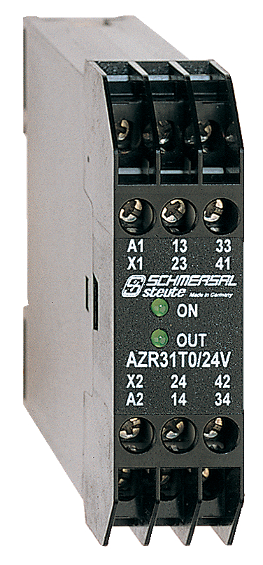
ID: kazr3f03
| 393.1 kB | .jpg | 132.644 x 284.692 mm - 376 x 807 px - 72 dpi
| 158.9 kB | .png | 74.083 x 158.75 mm - 210 x 450 px - 72 dpi
| 59.6 kB | .jpg | 57.503 x 123.47200000000001 mm - 163 x 350 px - 72 dpi
| 40.9 kB | .png | 74.083 x 74.083 mm - 210 x 210 px - 72 dpi
| 14.9 MB | .png | 166.55700000000002 x 357.432 mm - 2000 x 4292 px - 305 dpi
Schmersal India Pvt. Ltd., Plot No - G-7/1, Ranjangaon MIDC, Tal. - Shirur, Dist.- Pune 412 220
The details and data referred to have been carefully checked. Images may diverge from original. Further technical data can be found in the manual. Technical amendments and errors possible.
Generated at: 15/04/2026, 1:51 pm