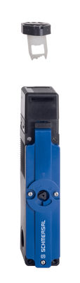
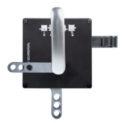
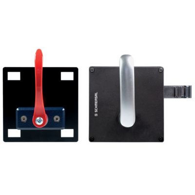
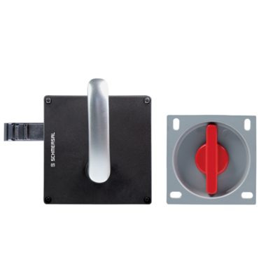
MS-AZM 200ST-T-1P2PWA-2568
MS-AZM 200ST-T-1P2PWA-2568
| Product type description: AZM 200(1)(2)-T-(3)(4) |
| (1) | |
| without | Guard locking monitored > |
| B | Actuator monitored |
| (2) | |
| SK | Screw connection |
| CC | Cage clamp |
| ST1 | Connector M23 x 1, (8+1 pole) |
| ST2 | Connector M12 x 1, 8 pole |
| (3) | |
| 1P2P | 1 serial diagnostic output and 2 p-type safety outputs |
| 1P2PW | same as 1P2P, combined diagnostic signal: guard system closed and interlock locked |
| SD2P | serial diagnostic output and 2 p-type safety outputs |
| (4) | |
| without | Power to unlock |
| A | Power to lock |
- Guard locking monitored
- Connector M23 12-pole,
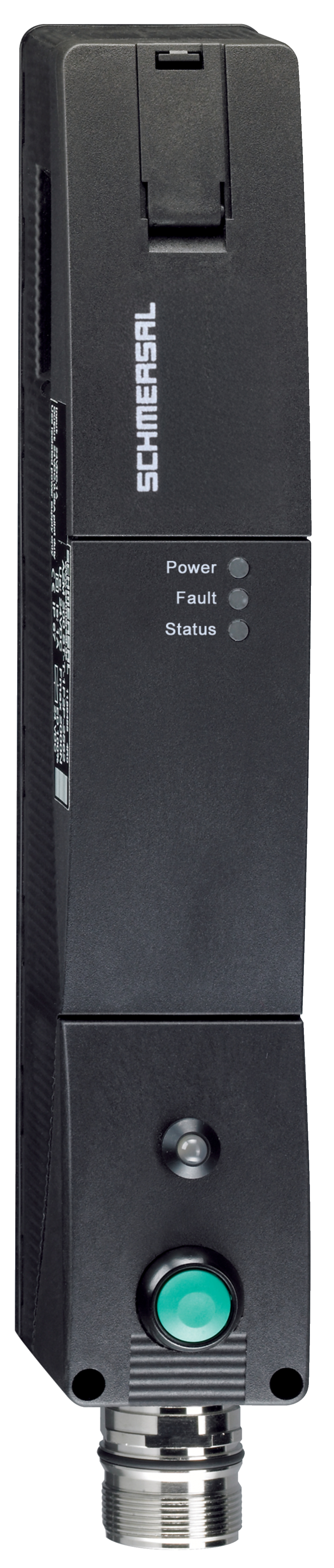
- Idle assignable pushbutton and LED
- Thermoplastic enclosure
- Electronic contact-free, coded system
- Max. length of the sensor chain 200 m
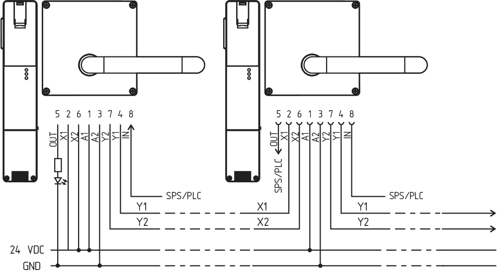
- Self-monitoring series-wiring
- 3 LEDs to show operating conditions
- Sensor technology permits an offset between actuator and interlock of ± 5 mm vertically and ± 1,5 mm horizontally
- Intelligent diagnosis
- Manual release
Ordering data
| Note (Delivery capacity) |
Not available! |
| Product type description |
MS-AZM 200ST-T-1P2PWA-2568 |
| Article number (order number) |
103005000 |
| EAN (European Article Number) |
4030661433431 |
| eCl@ss number, version 12.0 |
27-27-26-03 |
| eCl@ss number, version 11.0 |
27-27-26-03 |
| eCl@ss number, version 9.0 |
27-27-26-03 |
| ETIM number, version 7.0 |
EC002593 |
| ETIM number, version 6.0 |
EC002593 |
General data
| Standards |
EN ISO 13849-1 EN IEC 60947-5-1 EN IEC 61508 |
| Coding |
Universal coding |
| Coding level according to EN ISO 14119 |
Low |
| Working principle |
inductive |
| Housing material |
Glass-fibre, reinforced thermoplastic |
| Reaction time, maximum |
60 ms |
| Duration of risk, maximum |
120 ms |
| Gross weight |
734 g |
General data - Features
| Power to lock |
Yes |
| Solenoid interlock monitored |
Yes |
| Manual release |
Yes |
| Short circuit detection |
Yes |
| Cross-circuit detection |
Yes |
| Series-wiring |
Yes |
| Idle assignable pushbutton |
Yes |
| Freely assignable LED |
Yes |
| Safety functions |
Yes |
| Integral system diagnostics, status |
Yes |
| Number of safety contacts |
2 |
Safety classification
| Standards |
EN ISO 13849-1 EN IEC 60947-5-3 EN IEC 61508 |
| Mission time |
20 Year(s) |
Safety classification - Interlocking function
| Performance Level, up to |
e |
| Category |
4 |
| PFH value |
4.00 x 10⁻⁹ /h |
| PFD value |
1.00 x 10⁻⁴ |
| Safety Integrity Level (SIL), suitable for applications in |
3 |
| Mission time |
20 Year(s) |
Safety classification - Guard locking function
| Performance Level, up to |
d |
| Category |
2 |
| PFH value |
2.50 x 10⁻⁹ /h |
| PFD value |
2.20 x 10⁻⁴ |
| Safety Integrity Level (SIL), suitable for applications in |
2 |
| Mission time |
20 Year(s) |
Mechanical data
| Mechanical lifetime, minimum |
1,000,000 Operations |
| Holding force FZh in accordance with EN ISO 14119 |
2,000 N |
| Note (clamping force FZh) |
1,000 N when used with the AZ/AZM201-B30 actuator, for indoor use. |
| Holding force Fmax, maximum |
2,600 N |
| Note (clamping force Fmax) |
1.300 N in Verbindung mit einem Betätiger AZ/AZM201-B30 für Innenanbau. |
| Latching force |
30 N |
| Actuating speed, maximum |
0.2 m/s |
| Tightening torque of the fastening screws for the housing cover, minimum |
0.7 Nm |
| Tightening torque of the fastening screws for the housing cover, maximum |
1 Nm |
| Note |
Torx T10 |
Mechanical data - Connection technique
| Termination |
Connector M23, 12-pole |
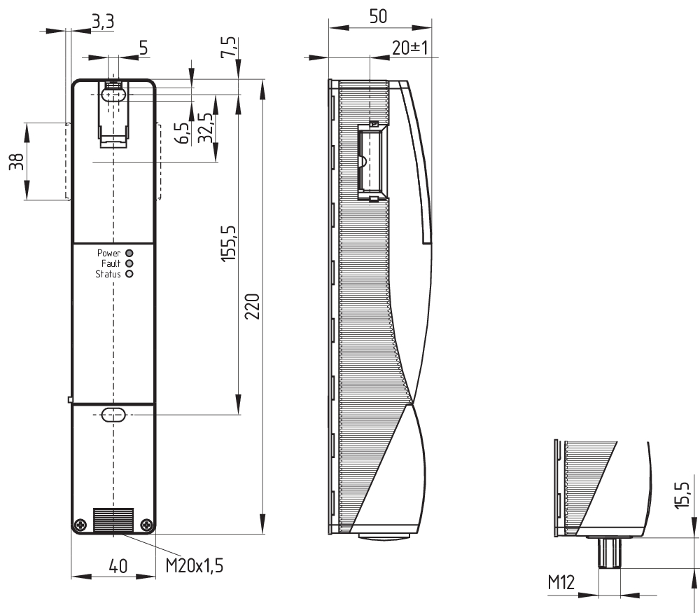
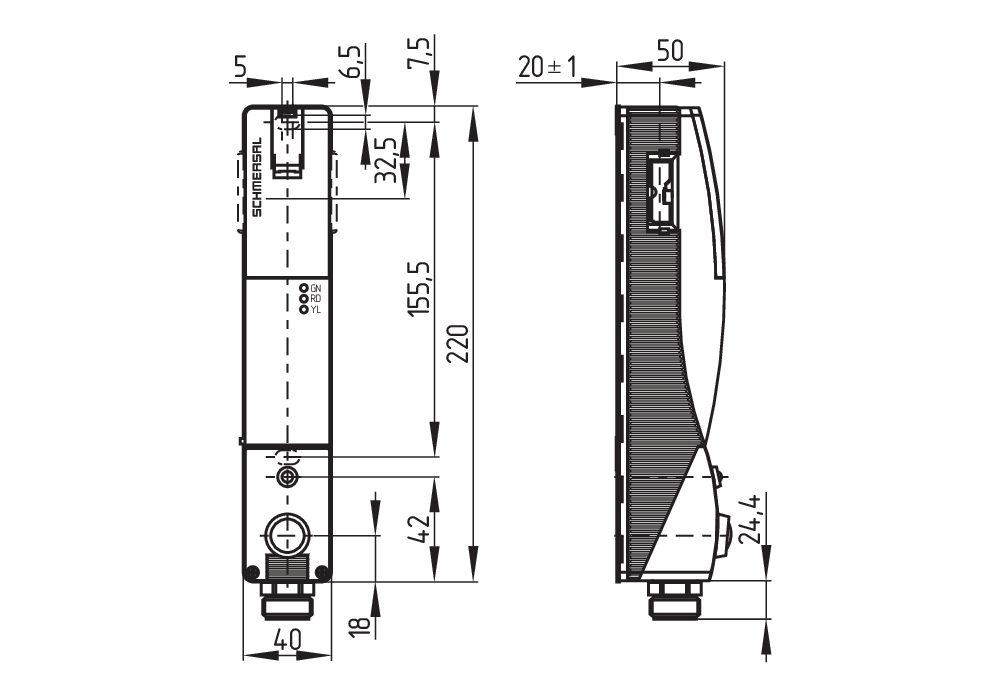
Mechanical data - Dimensions
| Length of sensor |
50 mm |
| Width of sensor |
40 mm |
| Height of sensor |
220 mm |
Ambient conditions
| IP Degree of protection |
IP67 |
| Ambient temperature |
-25 ... +50 °C |
| Storage and transport temperature |
-25 ... +85 °C |
| Relative humidity, minimum |
30 % |
| Relative humidity, maximum |
95 % |
| Note (Relative humidity) |
non-condensing |
| Resistance to vibrations |
10 … 55 Hz, amplitude 1 mm |
| Restistance to shock |
30 g / 11 ms |
| Protection class |
II |
Ambient conditions - Insulation values
| Rated insulation voltage Ui |
32 VDC |
| Rated impulse withstand voltage Uimp |
0.8 kV |
| Overvoltage category |
III |
| Degree of pollution |
3 |
Electrical data
| Operating voltage |
24 VDC -15 % / +10 % (stabilised PELV power supply) |
| No-load supply current I0, typical |
600 mA |
| Rated operating voltage |
24 VDC |
| Operating current |
1,200 mA |
| Time to readiness, maximum |
4,000 ms |
| Switching frequency, approx. |
1 Hz |
| Electrical fuse rating, maximum |
4 A |
Electrical data - Magnet control
| Switching thresholds |
-3 V … 5 V (Low) 15 V … 30 V (High) |
| Magnet switch-on time |
100 % |
Electrical data - Safety digital inputs
| Switching thresholds |
−3 V … 5 V (Low) 15 V … 30 V (High) |
| Current consumption at 24 V |
5 mA |
Electrical data - Safety digital outputs
| Rated operating current (safety outputs) |
250 mA |
| Voltage drop Ud, maximum |
4 V |
| Leakage current Ir, maximum |
0.5 mA |
| Voltage, Utilisation category DC-13 |
24 VDC |
| Current, Utilisation category DC-13 |
0.25 A |
Electrical data - Diagnostic outputs
| Operating current |
50 mA |
| Voltage drop Ud, maximum |
4 V |
| Voltage, Utilisation category DC-13 |
24 VDC |
| Current, Utilisation category DC-13 |
0.05 A |
Status indication
| Note (LED switching conditions display) |
Operating condition: LED green Error / functional defect: LED red Supply voltage UB: LED green |
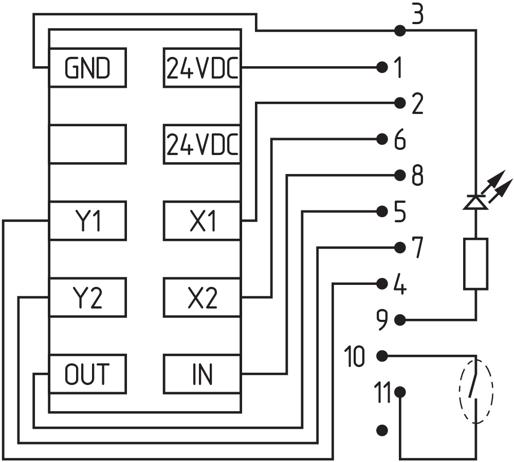
Pin assignment
| PIN 1 |
A1 Supply voltage UB |
| PIN 2 |
X1 Safety input 1 |
| PIN 3 |
A2 GND |
| PIN 4 |
Y1 Safety output 1 |
| PIN 5 |
OUT Diagnostic output |
| PIN 6 |
X2 Safety input 2 |
| PIN 7 |
Y2 Safety output 2 |
| PIN 8 |
IN Solenoid control |
| PIN 9 |
white LED |
| PIN 10 |
Key button |
| PIN 11 |
Key button |
| PIN 12 |
Not used |
Scope of delivery
| Scope of delivery |
Actuator must be ordered separately. Triangular key for AZM 200 |
Accessory
| Recommendation (actuator) |
AZ/AZM 200-B1 |
Note
| Note (General) |
As long as the actuating unit remains inserted in the solenoid interlock, the unlocked safety guard can be relocked. In this case, the safety outputs are re-enabled, so that the safety guard must not be opened. |
Language filter
Datasheet
Operating instructions and Declaration of conformity
Info
Wiring example (electr. wiring)
SISTEMA-VDMA library
Download the latest version of Adobe Reader
Product picture (catalogue individual photo)
ID: kazm2f28
| 10.6 kB | .jpg | 42.686 x 200.025 mm - 121 x 567 px - 72 dpi
| 1.9 MB | .jpg | 352.778 x 1656.2920000000001 mm - 1000 x 4695 px - 72 dpi
| 334.0 kB | .png | 74.083 x 347.839 mm - 210 x 986 px - 72 dpi
| 18.3 kB | .png | 74.083 x 74.083 mm - 210 x 210 px - 72 dpi
| 21.3 MB | .png | 169.333 x 795.105 mm - 2000 x 9391 px - 300 dpi
| 18.3 kB | .jpg | 26.458000000000002 x 123.47200000000001 mm - 75 x 350 px - 72 dpi
Dimensional drawing basic component
Diagram
Assembly example
Contact arrangement

Wiring example

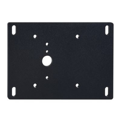
101188600 MP-AZ/AZM201
- Mounting plate for easy and quick assembly
- Metal, powder-coated

101194218 MP-AZ/AZM201-B30
- Mounting plate for easy and quick assembly
- Metal, powder-coated
- suitable for left and right hinged doors
101194224 MP-AZ/AZM201-P1
- Mounting plate for easy and quick assembly
- Metal, powder-coated
- suitable for left and right hinged doors

101185694 MP-AZ/AZM201-P20
- Mounting plate for easy and quick assembly
- Metal, powder-coated
- suitable for left and right hinged doors

101214126 MP-AZ/AZM201/BDF200-AZ/AZM201-B30
- Mounting plate for easy and quick assembly
- Metal, powder-coated
- suitable for left and right hinged doors

103004966 RF-AZM201-T
- Emergency exit retrofit kit
- Subsequent functional expansion of the solenoid interlock AZM201
103003543 RF-AZM201-N
- Emergency release retrofit kit
- Subsequent functional expansion of the solenoid interlock AZM201
- optional lead sealing possible

101194438 Lockout tag SZ 200
- Lockout tag with 5 circular holes
- Suitable for mounting inside and outside of the hazardous area
- To prevent inadvertent closing, e.g. during maintenance
- For complex plant
- Prevents actuation of the switch
103001074 RF-AZ/AZM201-B30-SZ
- enables the addition of an integrated lockout tag
- suitable for available B30 actuator systems
- Lockout tag with 3 circular holes
- For complex plant
- Prevents actuation of the switch

103051655 SZ201-1
- Suitable for mounting inside and outside of the hazardous area
- To prevent inadvertent closing, e.g. during maintenance
- For complex plant
- Prevents actuation of the switch
- Lockout tag with 6 circular holes

101196397 LOCKOUT TAG SZ 200-1
- Lockout tag with 6 circular holes
- Suitable for mounting inside and outside of the hazardous area
- To prevent inadvertent closing, e.g. during maintenance
- For complex plant
- Prevents actuation of the switch

101183465 AZ/AZM 200-B1-LT
- Actuators with return spring
- Actuator for sliding guards
- Tolerates up to max. 5 mm overtravel
101183466 AZ/AZM 200-B1-LTP0
- Actuators with return spring
- Actuator for sliding guards
- Tolerates up to max. 5 mm overtravel
101183469 AZ/AZM 200-B1-RT
- Actuators with return spring
- Actuator for sliding guards
- Tolerates up to max. 5 mm overtravel
101183470 AZ/AZM 200-B1-RTP0
- Actuators with return spring
- Actuator for sliding guards
- Tolerates up to max. 5 mm overtravel

101178681 AZ/AZM 200-B30-LTAG1
- Actuator for hinged guards
- With door detection sensor T
- Easy and intuitive operation
- No risk of injury from protruding actuator
- No supplementary door handles required
- Does not protrude into the door opening
- Various handles available
- Greater mechanical stability

101178668 AZ/AZM 200-B30-LTAG1P1
- One-hand emergency exit,
even in de-energised condition - Actuator for hinged guards
- With door detection sensor T
- Easy and intuitive operation
- No risk of injury from protruding actuator
- No supplementary door handles required
- Does not protrude into the door opening
- Various handles available
- Greater mechanical stability
101186150 AZ/AZM 200-B30-LTAG1P20
- One-hand emergency exit,
even in de-energised condition - Actuator for hinged guards
- With door detection sensor T
- Easy and intuitive operation
- No risk of injury from protruding actuator
- No supplementary door handles required
- Does not protrude into the door opening
- Various handles available
- Greater mechanical stability

101192102 AZ/AZM 200-B30-LTAG1P25
- One-hand emergency exit,
even in de-energised condition - Actuator for hinged guards
- With door detection sensor T
- Easy and intuitive operation
- No risk of injury from protruding actuator
- No supplementary door handles required
- Does not protrude into the door opening
- Various handles available
- Greater mechanical stability

101181137 AZ/AZM 200-B30-LTAG2
- Actuator for hinged guards
- With door detection sensor T
- Easy and intuitive operation
- No risk of injury from protruding actuator
- No supplementary door handles required
- Does not protrude into the door opening
- Various handles available
- Greater mechanical stability

101181141 AZ/AZM 200-B30-LTAG2P1
- One-hand emergency exit,
even in de-energised condition - Actuator for hinged guards
- With door detection sensor T
- Easy and intuitive operation
- No risk of injury from protruding actuator
- No supplementary door handles required
- Does not protrude into the door opening
- Various handles available
- Greater mechanical stability

101189020 AZ/AZM 200-B30-LTAG2P20
- One-hand emergency exit,
even in de-energised condition - Actuator for hinged guards
- With door detection sensor T
- Easy and intuitive operation
- No risk of injury from protruding actuator
- No supplementary door handles required
- Does not protrude into the door opening
- Various handles available
- Greater mechanical stability

101192106 AZ/AZM 200-B30-LTAG2P25
- One-hand emergency exit,
even in de-energised condition - Actuator for hinged guards
- With door detection sensor T
- Easy and intuitive operation
- No risk of injury from protruding actuator
- No supplementary door handles required
- Does not protrude into the door opening
- Various handles available
- Greater mechanical stability

101178680 AZ/AZM 200-B30-RTAG1
- Actuator for hinged guards
- With door detection sensor T
- Easy and intuitive operation
- No risk of injury from protruding actuator
- No supplementary door handles required
- Does not protrude into the door opening
- Various handles available
- Greater mechanical stability

101178738 AZ/AZM 200-B30-RTAG1P1
- One-hand emergency exit,
even in de-energised condition - Actuator for hinged guards
- With door detection sensor T
- Easy and intuitive operation
- No risk of injury from protruding actuator
- No supplementary door handles required
- Does not protrude into the door opening
- Various handles available
- Greater mechanical stability

101186144 AZ/AZM 200-B30-RTAG1P20
- One-hand emergency exit,
even in de-energised condition - Actuator for hinged guards
- With door detection sensor T
- Easy and intuitive operation
- No risk of injury from protruding actuator
- No supplementary door handles required
- Does not protrude into the door opening
- Various handles available
- Greater mechanical stability
101192103 AZ/AZM 200-B30-RTAG1P25
- One-hand emergency exit,
even in de-energised condition - Actuator for hinged guards
- With door detection sensor T
- Easy and intuitive operation
- No risk of injury from protruding actuator
- No supplementary door handles required
- Does not protrude into the door opening
- Various handles available
- Greater mechanical stability

101181139 AZ/AZM 200-B30-RTAG2
- Actuator for hinged guards
- With door detection sensor T
- Easy and intuitive operation
- No risk of injury from protruding actuator
- No supplementary door handles required
- Does not protrude into the door opening
- Various handles available
- Greater mechanical stability

101181143 AZ/AZM 200-B30-RTAG2P1
- One-hand emergency exit,
even in de-energised condition - Actuator for hinged guards
- With door detection sensor T
- Easy and intuitive operation
- No risk of injury from protruding actuator
- No supplementary door handles required
- Does not protrude into the door opening
- Various handles available
- Greater mechanical stability

101191659 AZ/AZM 200-B30-RTAG2P20
- One-hand emergency exit,
even in de-energised condition - Actuator for hinged guards
- With door detection sensor T
- Easy and intuitive operation
- No risk of injury from protruding actuator
- No supplementary door handles required
- Does not protrude into the door opening
- Various handles available
- Greater mechanical stability

101192104 AZ/AZM 200-B30-RTAG2P25
- One-hand emergency exit,
even in de-energised condition - Actuator for hinged guards
- With door detection sensor T
- Easy and intuitive operation
- No risk of injury from protruding actuator
- No supplementary door handles required
- Does not protrude into the door opening
- Various handles available
- Greater mechanical stability

103025498 AZM201Z-ST-T-1P2PW-A-2965-1
- Power to lock
- Thermoplastic enclosure
- Max. length of the sensor chain 200 m
- Self-monitoring series-wiring
- Coding in accordance to ISO 14119 by using RFID-Technology
- 3 LEDs to show operating conditions
- Sensor technology permits an offset between actuator and interlock of ± 5 mm vertically and ± 1,5 mm horizontally
- Suitable for hinged and sliding guards
- Intelligent diagnosis
- Manual release
- Protection class IP66, IP67
- High holding force 2000 N
- symmetrical construction form, assembly on 40mm profiles
- OSSD safety outputs
- Emergency exit / Emergency release suitable for retrofitting
Schmersal, Inc., 15 Skyline Drive, NY 10532 Hawthorne
The details and data referred to have been carefully checked. Images may diverge from original. Further technical data can be found in the manual. Technical amendments and errors possible.
Generated at: 2026-04-27, 12:52 p.m.
Recently viewed
EX-SHGV/ESS21S2/225/11033-3G/D