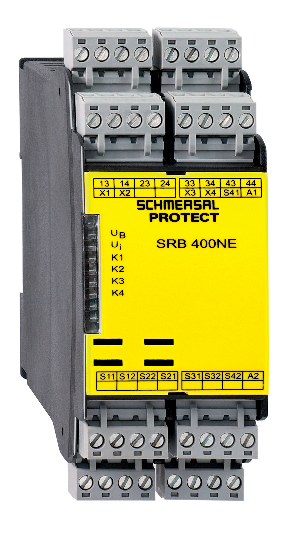
SRB400NE 24V
- Suitable for the signal processing of outputs with contact sensors
- Possibility to connect a non-contact end switch or speed reduction switch
- 2 safety contacts, switch-off level 1;
2 safety contacts, switch-off level 2
Ordering data
| Replacement article number |
101178528 |
| Product type description |
SRB400NE 24V |
| Article number (order number) |
101178394 |
| EAN (European Article Number) |
4250116202393 |
| eCl@ss number, version 12.0 |
27-37-18-19 |
| eCl@ss number, version 11.0 |
27-37-18-19 |
| eCl@ss number, version 9.0 |
27-37-18-19 |
| ETIM number, version 7.0 |
EC001449 |
| ETIM number, version 6.0 |
EC001449 |
Approvals - Standards
| Certificates |
cULus |
General data
| Standards |
EN IEC 62061 EN ISO 13849-1 EN IEC 60947-5-1 EN IEC 60947-5-3 EN IEC 60947-5-5 EN IEC 61508 EN IEC 60204-1 EN IEC 60947-1 |
| Climatic stress |
EN 60068-2-78 |
| Housing material |
Glass-fibre reinforced thermoplastic, ventilated |
| Gross weight |
350 g |
General data - Features
| Wire breakage detection |
Yes |
| Cross-circuit detection |
Yes |
| Removable Terminals |
Yes |
| Feedback circuit |
Yes |
| Automatic reset function |
Yes |
| Earth connection detection |
Yes |
| Integral system diagnostics, status |
Yes |
| Number of LEDs |
7 |
| Number of normally closed (NC) |
4 |
| Number of safety contacts |
4 |
Safety classification
| Standards |
EN IEC 60947-5-1 EN IEC 61508 |
| Stop-Category |
0 |
Safety classification - Relay outputs
| PFH value |
2.00 x 10⁻⁸ /h |
| Performance Level, stop 0, up to |
e |
| Category, Stop 0 |
4 |
| Diagnostic Coverage (DC) Level, Stop 0 |
≥ 99 % |
| Safety Integrity Level (SIL), Stop 0, suitable for applications in |
3 |
| Mission time |
20 Year(s) |
| Common Cause Failure (CCF), minimum |
65 |
Mechanical data
| Mechanical lifetime, minimum |
10,000,000 Operations |
| Mounting |
Snaps onto standard DIN rail to EN 60715 |
Mechanical data - Connection technique
| Terminal designations |
IEC/EN 60947-1 |
| Cable section, minimum |
0.25 mm² |
| Cable section, maximum |
2.5 mm² |
| Tightening torque of Clips |
0.6 Nm |
| Allowed type of cable |
solid single-wire flexible |
| Terminal (mechanical) |
Screw terminals |
Mechanical data - Dimensions
| Width |
45 mm |
| Height |
100 mm |
| Depth |
121 mm |
Ambient conditions
| Degree of protection of the enclosure |
IP40 |
| Degree of protection of the installation space |
IP54 |
| Degree of protection of clips or terminals |
IP20 |
| Ambient temperature |
-25 ... +45 °C |
| Storage and transport temperature |
-40 ... +85 °C |
| Resistance to vibrations |
10...55 Hz, Amplitude 0.35 mm, ± 15 % |
| Restistance to shock |
30 g / 11 ms |
Ambient conditions - Insulation values
| Rated impulse withstand voltage Uimp |
4 kV |
| Overvoltage category |
III |
| Degree of pollution |
2 |
Electrical data
| Frequency range |
50 Hz 60 Hz |
| Operating voltage |
24 VAC -15 % / +10 % |
| Ripple voltage |
10 % |
| Rated operating voltage |
24 VAC |
| Rated operating voltage |
24 VDC |
| Rated AC voltage for controls, 50 Hz, minimum |
20.4 VAC |
| Rated control voltage at AC 50 Hz, maximum |
26.4 VAC |
| Rated AC voltage for controls, 60 Hz, minimum |
20.4 VAC |
| Rated control voltage at AC 60 Hz, maximum |
26.4 VAC |
| Rated AC voltage for controls at DC minimum |
20.4 VDC |
| Rated control voltage at DC, maximum |
28.8 VDC |
| Electrical power consumption |
6 W |
| Electrical power consumption |
6 VA |
| Contact resistance, maximum |
0.1 Ω |
| Note (Contact resistance) |
in new state |
| Drop-out delay in case of power failure, typically |
80 ms |
| Drop-out delay in case of emergency, typically |
20 ms |
| Pull-in delay at automatic start, maximum, typically |
100 ms |
| Pull-in delay at RESET, typically |
20 ms |
| Material of the contacts, electrical |
Ag-Ni, self-cleaning, positive drive |
Electrical data - Safe relay outputs
| Voltage, Utilisation category AC-15 |
230 VAC |
| Current, Utilisation category AC-15 |
4 A |
| Voltage, Utilisation category DC-13 |
24 VDC |
| Current, Utilisation category DC-13 |
4 A |
| Switching capacity, minimum |
10 VDC |
| Switching capacity, minimum |
10 mA |
| Switching capacity, maximum |
250 VAC |
| Switching capacity, maximum |
8 A |
Electrical data - Digital inputs
| Conduction resistance, maximum |
40 Ω |
Electrical data - Relay outputs (auxiliary contacts)
| Switching capacity, maximum |
24 VDC |
| Switching capacity, maximum |
2 A |
Electrical data - Electromagnetic compatibility (EMC)
| EMC rating |
EMC-Directive |
Status indication
| Indicated operating states |
Position relay K2 Position relay K1 Internal operating voltage Ui Position relay K3 Position relay K5 |
Other data
| Note (applications) |
Safety sensor Guard system |
Note
| Note (General) |
Inductive loads (e.g. contactors, relays, etc.) are to be suppressed by means of a suitable circuit. |
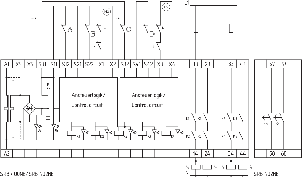
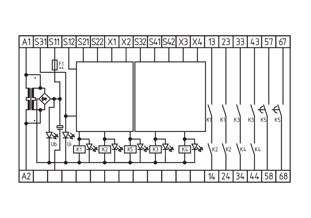
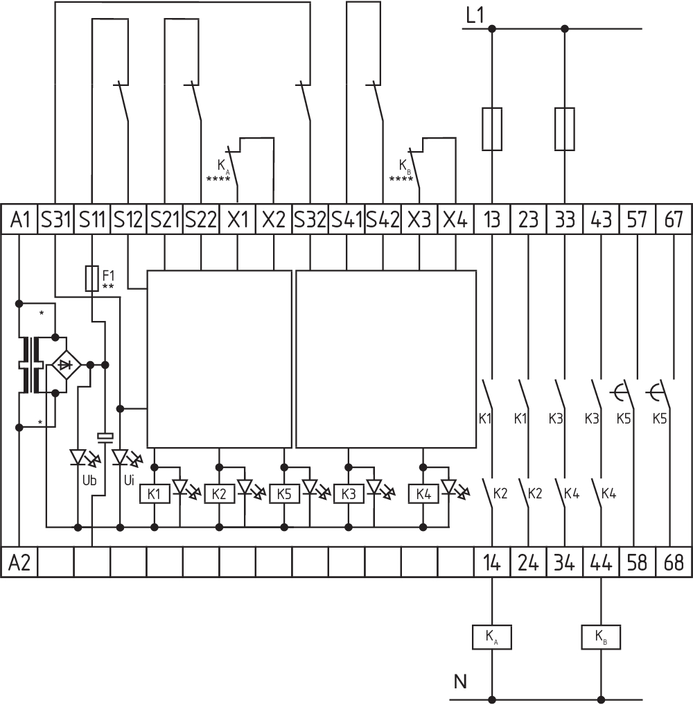
Wiring example
| Note (Wiring diagram) |
The control system recognises wire-breakage and earth faults in the monitoring circuit. The example shows a 1-channel control with contact A for a guard door monitor; of which at least one contact has positive break; with external reset button (R). Relay outputs: Suitable for 1 channel control, for increase in capacity or number of contacts by means of contactors or relays with positive-guided contacts. The wiring diagram is shown with non-actuated limit switches and in de-energised condition. (H2) = Feedback circuit |
Language filter
Datasheet
Operating instructions and Declaration of conformity
UL Certificate
Wiring example (electr. wiring)
SISTEMA-VDMA library
Download the latest version of Adobe Reader
Product picture (catalogue individual photo)
ID: ksrb4f08
| 1.4 MB | .jpg | 342.547 x 625.1220000000001 mm - 971 x 1772 px - 72 dpi
| 95.2 kB | .png | 74.083 x 135.114 mm - 210 x 383 px - 72 dpi
| 60.8 kB | .jpg | 67.733 x 123.47200000000001 mm - 192 x 350 px - 72 dpi
| 42.8 kB | .png | 74.083 x 74.083 mm - 210 x 210 px - 72 dpi
| 9.6 MB | .png | 169.333 x 308.949 mm - 2000 x 3649 px - 300 dpi
Wiring example
Wiring example
Wiring example
Symbol (technical standard)

Schmersal, Inc., 15 Skyline Drive, NY 10532 Hawthorne
The details and data referred to have been carefully checked. Images may diverge from original. Further technical data can be found in the manual. Technical amendments and errors possible.
Generated at: 4/18/2026, 2:17 PM