BN 650-RZ
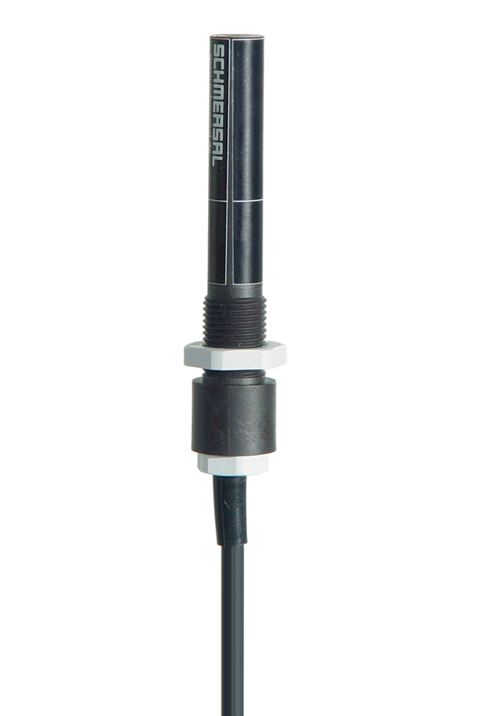
BN 650-RZ
Downloads
- With pre-wired cable
- Actuation from side
- with bias magnet
- Non-contact principle
- Long life
- Construction form Ø 13 mm
- Thermoplastic enclosure
- Actuating distance up to 60 mm depending on actuating magnet and version
- with central mounting
Ordering data
| Product type description |
BN 650-RZ |
| Article number (order number) |
101187283 |
| EAN (European Article Number) |
4030661335681 |
| eCl@ss number, version 12.0 |
27-27-43-02 |
| eCl@ss number, version 11.0 |
27-27-01-05 |
| eCl@ss number, version 9.0 |
27-27-01-05 |
| ETIM number, version 7.0 |
EC002544 |
| ETIM number, version 6.0 |
EC002544 |
General data
| Working principle |
Magnetic drive |
| Housing construction form |
Cylinder smooth |
| Housing material |
Glass-fibre, reinforced thermoplastic |
| Gross weight |
65 g |
General data - Features
| Latching |
Yes |
| Suitable for elevators |
Yes |
| bias magnet |
Yes |
| Cable sleeve |
Yes |
| Number of snap-in contacts |
1 |
Mechanical data
| Active area |
lateral |
| Actuating element |
Magnet |
| Mechanical lifetime, minimum |
100,000,000 Operations |
| Actuating speed, maximum |
18 m/s |
| Mounting |
central with threated flange |
| Tightening torque of nuts, maximum |
3 Nm |
Mechanical data - Switching distances
| Switching distance Sn |
BP 10N = 15 mm BP 10S = 15 mm 2 x BP 10N = 20 mm 2 x BP 10S = 20 mm BP 15N = 17 mm BP 15S = 17 mm 2 x BP 15/2N = 22 mm 2 x BP 15/2S = 22 mm BP 34S = 15 ... 30 mm BP 20N = 25 mm BP 20S = 25 mm BP 31N = 25 mm BP 31S = 25 mm BP 11N = 15 mm BP 11S = 15 mm 2 x BP 11N = 25 mm 2 x BP 11S = 25 mm BP 12N = 20 mm BP 12S = 20 mm 2 x BP 12N = 10 ... 30 mm 2 x BP 12S = 10 ... 30 mm BP 21N = 15 ... 45 mm BP 21S = 15 ... 45 mm 2 x BP 21N = 20 ... 60 mm 2 x BP 21S = 20 ... 60 mm BP 34N = 15 ... 30 mm 10 mm … 60 mm |
| Note (Switching distance Sn) |
Actuating distance up to 60 mm depending on actuating magnet and version. The specified switching distances are applicable for the actuation of individually mounted components without ferromagnetic influence. A change of the distance, either positive or negative, is possible due to ferromagnetic influences. The mutual interference between multiple actuating magnets must be observed. |
| Note (switching distance) |
All switching distances in accordance EN IEC 60947-5-2 |
| Repeat accuracy R |
0.3 mm |
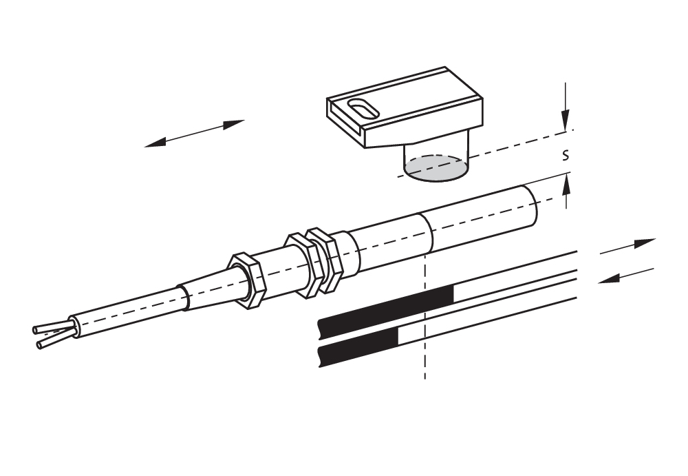
Mechanical data - Connection technique
| Length of cable |
1 m |
| Cable entry |
PG9 |
| Termination |
Pre-wired cable |
| Number of cable wires |
2 |
| Wire cross-section |
0.25 mm2 |
| Wire cross-section |
23 AWG |
| Material of the Cable mantle |
PVC |
| Cable type |
LiYY |
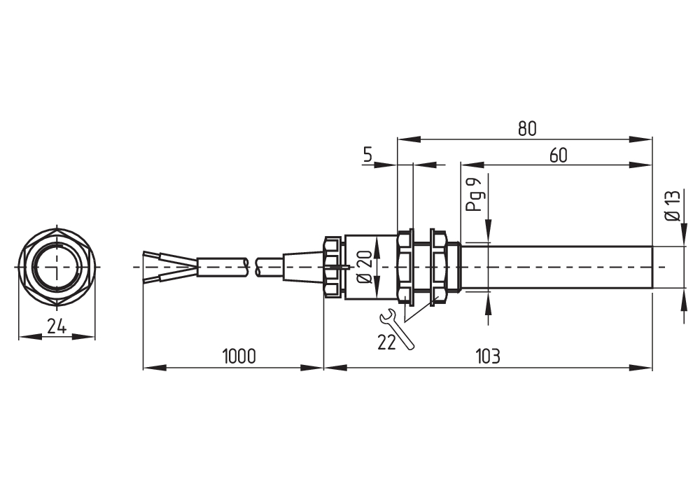
Mechanical data - Dimensions
| Diameter of sensor |
13 mm |
| width across flats |
22 BK |
| Length of sensor |
103 mm |
Ambient conditions
| Degree of protection |
IP67 |
| Ambient temperature |
-25 ... +70 °C |
| Resistance to vibrations |
10 … 55 Hz, amplitude 1 mm |
| Restistance to shock |
30 g / 11 ms |
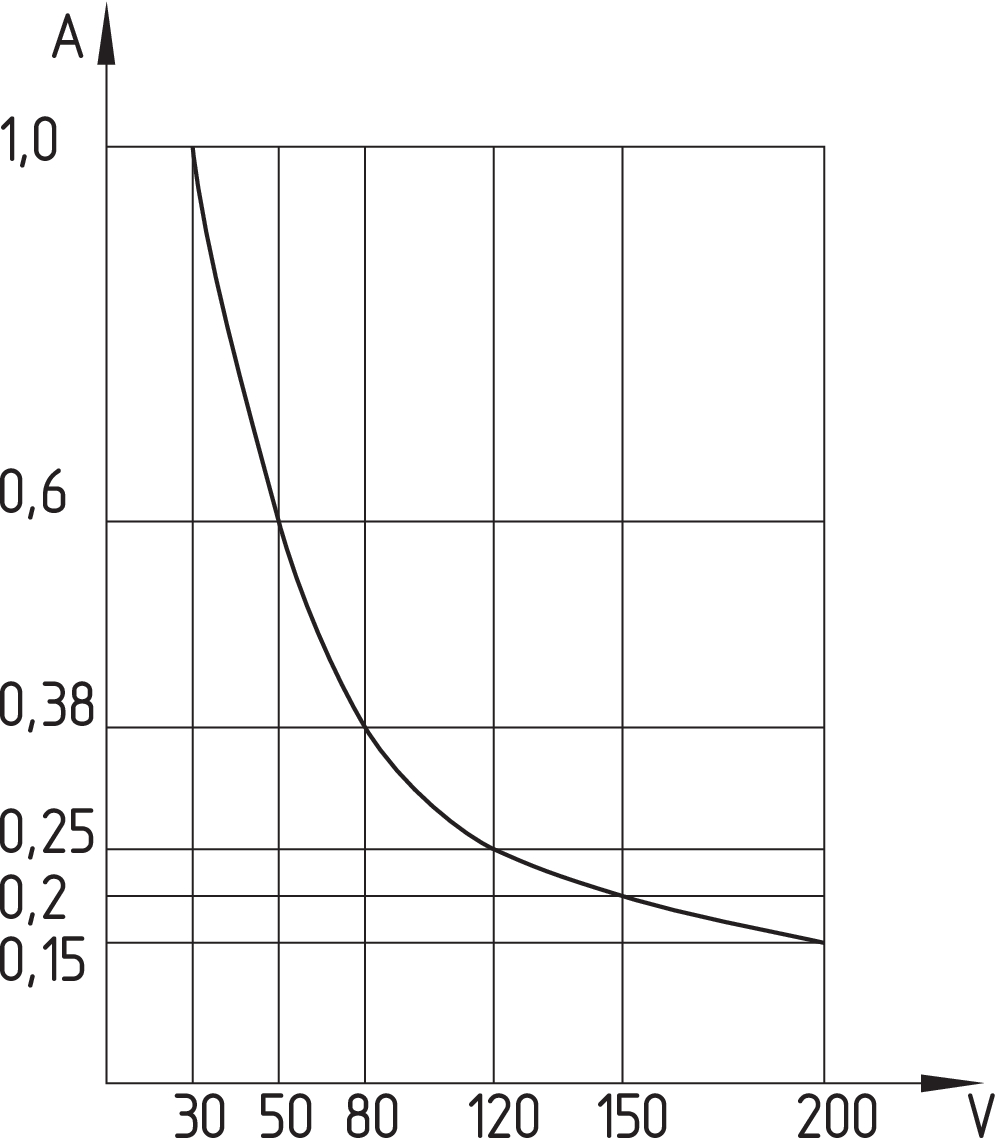
Electrical data
| Switching voltage, maximum |
200 VAC |
| Switching voltage, maximum |
200 VDC |
| Switching current, maximum |
1 A |
| Switching capacity, maximum |
30 W |
| Switching capacity, maximum |
30 VA |
| Switching principle |
Latching |
| Bounce duration, maximum |
0.2 ms |
| Switching frequency, maximum |
300 Hz |
| Maximale Schalthäufigkeit |
1,080,000 /h |
Scope of delivery
| Scope of delivery |
Actuator must be ordered separately. |
Accessory
| Recommendation (actuator) |
BP 10 S 2x BP 10 S BP 15 S BP 34 S BP 20 S BP 31 S BP 11 S 2x BP 11 S BP 12 S BP 21 S 2x BP 21 S BE 20 S BP 10 N 2x BP 10 N BP 15 N 2 x BP 15/2 N 2x BP 15/2 S BP 34 N BP 20 N BP 31 N BP 11 N 2x BP 11 N BP 12 N 2x BP 12 N 2x BP 12 S BP 21 N 2x BP 21 N BE 20 N |
| Recommendation (actuator, lift switchgear) |
BP 10 2 x BP 15/2 2 x BP 15 2 x BP 10 BP 15 BP 34 |
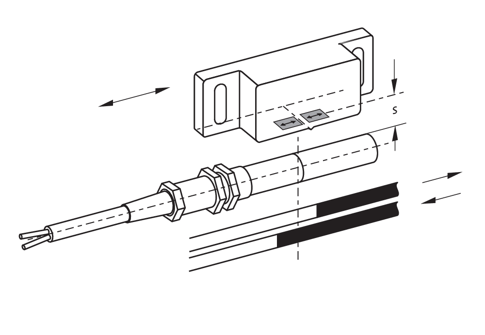
Note
| Note (General) |
The opening and closing functions depend on the direction of actuation, the actuating magnets and the polarity of the actuating magnets. When the switches and actuators come together, the colours must coincide: Red (S) to red (S) and green (N) to green (N). This does not apply to the bistable contact. |
Language filter
Datasheet
Mounting and wiring instructions
Declaration of conformity (EC)
Info
Download the latest version of Adobe Reader
Product picture (catalogue individual photo)
ID: kbn65f03
| 170.8 kB | .jpg | 352.778 x 518.231 mm - 1000 x 1469 px - 72 dpi
| 23.4 kB | .png | 74.083 x 108.656 mm - 210 x 308 px - 72 dpi
| 15.2 kB | .jpg | 83.961 x 123.47200000000001 mm - 238 x 350 px - 72 dpi
| 10.7 kB | .png | 74.083 x 74.083 mm - 210 x 210 px - 72 dpi
| 1.7 MB | .png | 166.55700000000002 x 244.673 mm - 2000 x 2938 px - 305 dpi
Dimensional drawing basic component
Switch travel diagram

Switch travel diagram
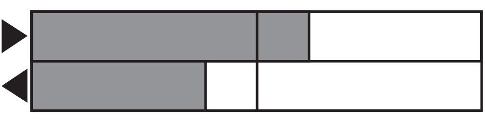
Diagram
Diagram
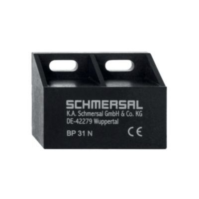
101057520 BP 31 N
- thermoplastic enclosure
- N-pole marked green
- Suitable for mounting on ferrous material with a distance of 20 mm

101057521 BP 31 S
- thermoplastic enclosure
- S-pole marked red
- Suitable for mounting on ferrous material with a distance of 20 mm

101057532 BP 12 S
- -metal housing
- S-pole marked red
- Suitable for mounting on ferrous material
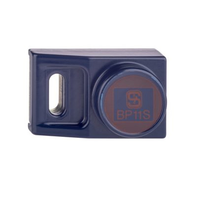
101057533 BP 11 S
- -metal housing
- S-pole marked red
- Suitable for mounting on ferrous material

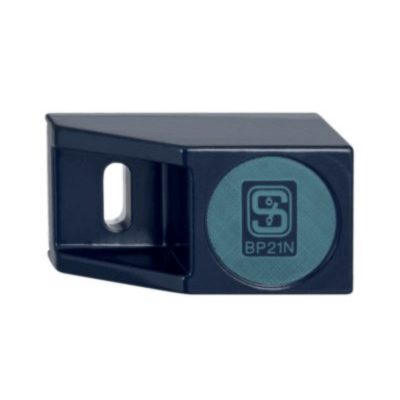
101057534 BP 21 S
- -metal housing
- S-pole marked red
- Suitable for mounting on ferrous material
101057536 BP 21 N
- -metal housing
- N-pole marked green
- Suitable for mounting on ferrous material

101057538 BP 20 N
- -metal housing
- N-pole marked green
- Suitable for mounting on ferrous material with a distance of 20 mm

101057541 BP 20 S
- -metal housing
- S-pole marked red
- Suitable for mounting on ferrous material with a distance of 20 mm
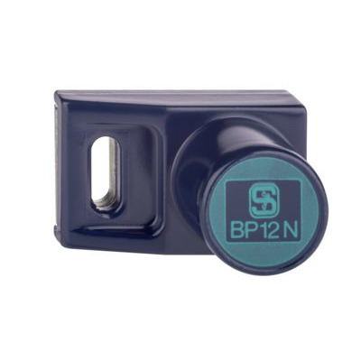
101059917 BP 12 N
- -metal housing
- N-pole marked green
- Suitable for mounting on ferrous material

101059923 BP 11 N
- -metal housing
- N-pole marked green
- Suitable for mounting on ferrous material
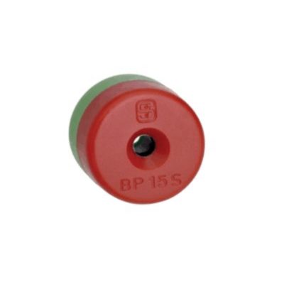
101060163 BP 15
- thermoplastic enclosure
- N-pole marked green
- S-pole marked red
- Suitable for mounting on ferrous material with a distance of 18 mm
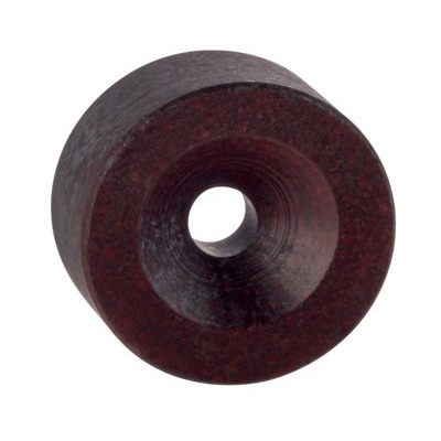
101060165 BP 15/2
- Unenclosed
- Polarity stamped in
- Suitable for mounting on ferrous material with a distance of 18 mm
Schmersal, Inc., 15 Skyline Drive, NY 10532 Hawthorne
The details and data referred to have been carefully checked. Images may diverge from original. Further technical data can be found in the manual. Technical amendments and errors possible.
Generated at: 4/17/2026, 5:06 PM