SRB207AN/1-230VAC
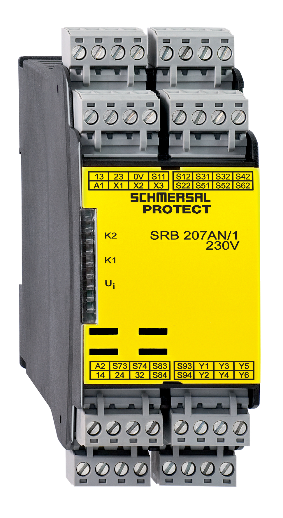
SRB207AN/1-230VAC
Downloads
- Suitable for the signal processing of outputs with contact sensors
- Suitable for the signal processing of outputs with contact sensors
- 2 safety contacts, STOP 0
- 6 Signalling outputs
- Multi-evaluation of up to 6 safety guards
Ordering data
| Note (Delivery capacity) |
Not available! |
| Product type description |
SRB207AN/1-230VAC |
| Article number (order number) |
101176606 |
| EAN (European Article Number) |
4250116202034 |
| eCl@ss number, version 12.0 |
27-37-18-19 |
| eCl@ss number, version 11.0 |
27-37-18-19 |
| eCl@ss number, version 9.0 |
27-37-18-19 |
| ETIM number, version 7.0 |
EC001449 |
| ETIM number, version 6.0 |
EC001449 |
Approvals - Standards
| Certificates |
cULus |
General data
| Standards |
EN IEC 62061 EN ISO 13849-1 EN IEC 60947-5-1 EN IEC 60947-5-3 EN IEC 60947-5-5 EN IEC 61508 EN IEC 60204-1 EN IEC 60947-1 |
| Climatic stress |
EN 60068-2-78 |
| Housing material |
Glass-fibre reinforced thermoplastic, ventilated |
| Gross weight |
400 g |
General data - Features
| Electronic Fuse |
Yes |
| Wire breakage detection |
Yes |
| Cross-circuit detection |
Yes |
| Removable Terminals |
Yes |
| Start input |
Yes |
| Feedback circuit |
Yes |
| Automatic reset function |
Yes |
| Reset edge detection |
Yes |
| Earth connection detection |
Yes |
| Integral system diagnostics, status |
Yes |
| Number of auxiliary contacts |
0 |
| Number of LEDs |
3 |
| Number of normally closed (NC) |
6 |
| Number of normally open (NO) |
6 |
| Number of safety contacts |
2 |
| Number of signalling outputs |
6 |
Safety classification
| Standards |
EN IEC 60947-5-1 EN IEC 61508 |
| Stop-Category |
0 |
Safety classification - Relay outputs
| Performance Level, stop 0, up to |
d |
| Category, Stop 0 |
3 |
| Diagnostic Coverage (DC) Level, Stop 0 |
≥ 99 % |
| PFH value, Stop 0 |
2.00 x 10⁻⁷ /h |
| Safety Integrity Level (SIL), Stop 0, suitable for applications in |
2 |
| Mission time |
20 Year(s) |
| Common Cause Failure (CCF), minimum |
65 |
Mechanical data
| Mechanical lifetime, minimum |
10,000,000 Operations |
| Mounting |
Snaps onto standard DIN rail to EN 60715 |
Mechanical data - Connection technique
| Terminal designations |
IEC/EN 60947-1 |
| Cable section, minimum |
0.25 mm² |
| Cable section, maximum |
2.5 mm² |
| Tightening torque of Clips |
0.6 Nm |
| Allowed type of cable |
solid single-wire flexible |
| Terminal (mechanical) |
Screw terminals |
Mechanical data - Dimensions
| Width |
45 mm |
| Height |
100 mm |
| Depth |
121 mm |
Ambient conditions
| Degree of protection of the enclosure |
IP40 |
| Degree of protection of the installation space |
IP54 |
| Degree of protection of clips or terminals |
IP20 |
| Ambient temperature |
-25 ... +45 °C |
| Storage and transport temperature |
-40 ... +85 °C |
| Resistance to vibrations |
10...55 Hz, Amplitude 0.35 mm, ± 15 % |
| Restistance to shock |
10 g / 11 ms |
Ambient conditions - Insulation values
| Rated impulse withstand voltage Uimp |
4 kV |
| Overvoltage category |
II |
| Degree of pollution |
2 |
Electrical data
| Frequency range |
50 Hz 60 Hz |
| Operating voltage |
48 ... 240 VAC |
| Type of voltage range |
AC |
| Rated operating voltage |
48 ... 240 VAC |
| Rated AC voltage for controls, 50 Hz, minimum |
48 VAC |
| Rated control voltage at AC 50 Hz, maximum |
240 VAC |
| Rated AC voltage for controls, 60 Hz, minimum |
48 VAC |
| Rated control voltage at AC 60 Hz, maximum |
240 VAC |
| Utilisation category AC-15 |
230 VAC |
| Utilisation category AC-15 |
6 A |
| Utilisation category DC-13 |
24 VDC |
| Utilisation category DC-13 |
6 A |
| Electrical power consumption |
6.8 W |
| Contact resistance, maximum |
0.1 Ω |
| Note (Contact resistance) |
in new state |
| Drop-out delay in case of "emergency stop", maximum |
20 ms |
| Pull-in delay at automatic start, maximum, typically |
120 ms |
| Pull-in delay at RESET, typically |
30 ms |
| Material of the contacts, electrical |
AgSn0. self-cleaning, positive drive |
Electrical data - Digital inputs
| Conduction resistance, maximum |
40 Ω |
Electrical data - Electromagnetic compatibility (EMC)
| EMC rating |
EMC-Directive |
Status indication
| Indicated operating states |
Position relay K2 Position relay K1 Internal operating voltage Ui |
Other data
| Note (applications) |
Safety sensor Guard system Emergency-Stop button Pull-wire emergency stop switches |
Note
| Note (General) |
Inductive loads (e.g. contactors, relays, etc.) are to be suppressed by means of a suitable circuit. |
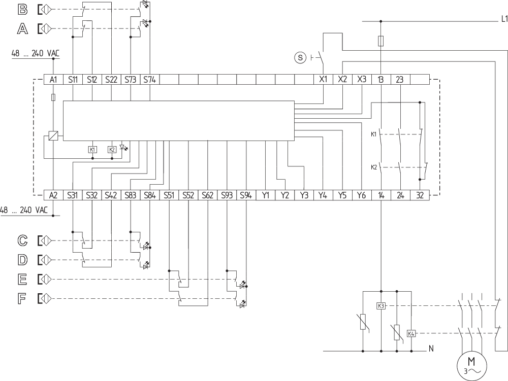
Wiring example
| Note (Wiring diagram) |
The wiring diagram is shown with guard doors closed and in de-energised condition. The feedback circuit monitors the position of the contactors K3 and K4. Automatic start: The automatic start is programmed by connecting the feedback circuit to the terminals X1/X3. If the feedback circuit is not required, establish a bridge. To secure 6 guard doors up to PL d and Category 3 Monitoring 6 guard door(s), each with a magnetic safety sensor of the BNS range Start button (S) with edge detection |
Language filter
Datasheet
Operating instructions and Declaration of conformity
UL Certificate
Download the latest version of Adobe Reader
Product picture (catalogue individual photo)
ID: ksrb2f32
| 1.4 MB | .jpg | 342.547 x 625.1220000000001 mm - 971 x 1772 px - 72 dpi
| 94.9 kB | .png | 74.083 x 135.114 mm - 210 x 383 px - 72 dpi
| 60.8 kB | .jpg | 67.733 x 123.47200000000001 mm - 192 x 350 px - 72 dpi
| 42.9 kB | .png | 74.083 x 74.083 mm - 210 x 210 px - 72 dpi
| 9.3 MB | .png | 169.333 x 308.949 mm - 2000 x 3649 px - 300 dpi
Wiring example
Symbol (technical standard)

K.A. Schmersal GmbH & Co. KG, Möddinghofe 30, 42279 Wuppertal
The details and data referred to have been carefully checked. Images may diverge from original. Further technical data can be found in the manual. Technical amendments and errors possible.
Generated at: 17/04/2026, 18:38
Recently viewed

AZ 16-STS30-04

RS655-Z22-G024

AZ 16 ZVRK-ST

RWSE4K.1

MP-AZ/AZM201-B30

UAM-5C20C